We turn now to the carrier signal, seeking ways to make it more controllable. We would particularly like to be able to slide the spectral energy continuously up and down in frequency. Simply ramping the frequency of the carrier oscillator will not accomplish this, since the spectra won't be harmonic except when the carrier is an integer multiple of the fundamental frequency.
In the stretched wavetable approach we can accomplish this simply by sampling a sinusoid and transposing it to the desired ``pitch". The transposed pitch isn't heard as a periodicity since the wavetable itself is read periodically at the fundamental frequency. Instead, the sinusoid is transposed as a spectral envelope.
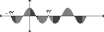
Figure 6.7 shows a carrier signal produced in this way, tuned to produce a formant centered at 1.5 times the fundamental frequency. The signal has no outright discontinuity at the phase wraparound frequency, but it does have a discontinuity in slope, which, if not removed by applying a suitable modulation signal, would have very audible high-frequency components.
 |
Using this idea we can make a complete description of how to use
the block diagram of Figure 6.3
to produce a desired formant. The wavetable lookup on the left hand
side would hold a sinusoid (placed symmetrically so that the phase
is zero at the center of the wavetable). The right-hand-side
wavetable would hold a Hann or other appropriate window function.
If we desire the fundamental frequency to be ![]() , the formant center frequency to be
, the formant center frequency to be ![]() , and the bandwidth to be
, and the bandwidth to be ![]() , we
set the ``stretch" parameter to the center frequency
quotient defined as
, we
set the ``stretch" parameter to the center frequency
quotient defined as
![]() , and the index of
modulation to the bandwidth quotient,
, and the index of
modulation to the bandwidth quotient,
![]() .
.
The output signal is simply a sample of a cosine wave at the desired center frequency, repeated at the (unrelated in general) desired period, and windowed to take out the discontinuities at period boundaries.
Although we aren't able to derive this result yet (we will need Fourier analysis), it will turn out that, in the main lobe of the formant, the phases are all zero at the center of the waveform (i.e., the components are all cosines if we consider the phase to be zero at the center of the waveform). This means we may superpose any number of these formants to build a more complex spectrum and the amplitudes of the partials will combine by addition. (The sidelobes don't behave so well: they are alternately of opposite sign and will produce cancellation patterns; but we can often just shrug them off as a small, uncontrollable, residual signal.)
This method leads to an interesting generalization, which is to take a sequence of recorded wavetables, align all their component phases to those of cosines, and use them in place of the cosine function as the carrier signal. The phase alignment is necessary to allow coherent cross-fading between samples so that the spectral envelope can change smoothly. If, for example, we use successive snippets of a vocal sample as input, we get a strikingly effective vocoder; see Section 9.6.
Another technique for making carrier signals that can be slid
continuously up and down in frequency while maintaining a
fundamental frequency is simply to cross-fade between harmonics.
The carrier signal is then:
The simplest way of making a control interface for this
synthesis technique would be to use ramps to update ![]() and
and ![]() , and then to compute
, and then to compute
![]() and
and ![]() as audio signals
from the ramped, smoothly varying
as audio signals
from the ramped, smoothly varying ![]() and
and
![]() . Oddly enough, despite the fact that
. Oddly enough, despite the fact that
![]() ,
, ![]() , and
, and ![]() are
discontinuous functions of
are
discontinuous functions of
![]() , the carrier
, the carrier ![]() turns out to vary continuously with
turns out to vary continuously with
![]() , and so if the desired center
frequency
, and so if the desired center
frequency ![]() is ramped from value to value
the result is a continuous sweep in center frequency. However, more
work is needed if discontinuous changes in center frequency are
needed. This is not an unreasonable thing to wish for, being
analogous to changing the frequency of an oscillator
discontinuously.
is ramped from value to value
the result is a continuous sweep in center frequency. However, more
work is needed if discontinuous changes in center frequency are
needed. This is not an unreasonable thing to wish for, being
analogous to changing the frequency of an oscillator
discontinuously.
There turns out to be a good way to accomodate this. The trick
to updating ![]() and
and ![]() is to note that
is to note that
![]() whenever
whenever ![]() is a
multiple of
is a
multiple of ![]() , regardless of the choice of
, regardless of the choice of
![]() ,
, ![]() , and
, and ![]() as long
as
as long
as ![]() . Hence, we may make discontinuous
changes in
. Hence, we may make discontinuous
changes in ![]() ,
, ![]() , and
, and ![]() once per period (right when the phase is a multiple of
once per period (right when the phase is a multiple of ![]() ), without making discontinuities in the carrier
signal.
), without making discontinuities in the carrier
signal.
In the specific case of FM, if we wish we can now go back and
modify the original formulation to: