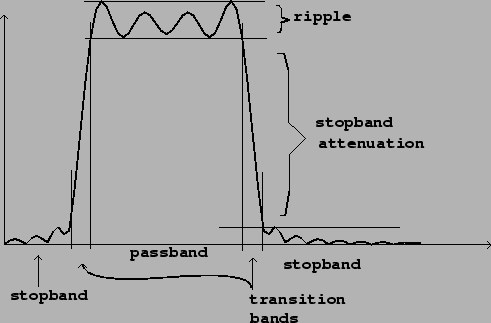
A band-pass filter admits frequencies within a given band, rejecting frequencies below it and above it. Much the same terminology as before may be used to describe a band-pass filter, as shown in figure 8.3. A stop-band filter does the reverse, rejecting frequencies withing the band and letting through frequencies outside it.
 |
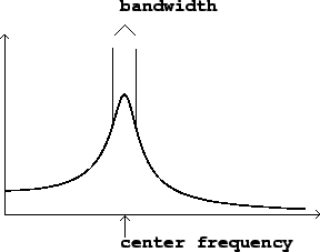
In practice, a simpler language is often used
for describing bandpass filters, as shown in Figure 8.4. Here there are only two controls: a center frequency and a bandwidth. The passband is considered to be
the region where the filter's output has at least half the power
(![]() times the gain) of its peak. The
bandwidth is the width, in frequency units, of the passband. The
center frequency is the point of maximum gain, which is
approximately the midpoint of the passband.
times the gain) of its peak. The
bandwidth is the width, in frequency units, of the passband. The
center frequency is the point of maximum gain, which is
approximately the midpoint of the passband.