 |
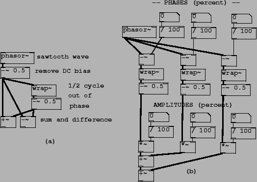
Patch J01.even.odd.pd (Figure 10.12 part a) shows how to combine sawtooth waves
in pairs to extract the even and odd harmonics. The resulting
waveforms are as shown in Figure ![]() .
Patch J02.trapezoids.pd (part b) demonstrates combining three
sawtooth waves at arbitrary phases and amplitudes; the resulting
classic waveform has up to three jumps and no corners. The three
line segments are horizontal as long as the three jumps add to
zero; otherwise the segments are sloped to make up for the the
unbalanced jumps so that the result repeats from one period to the
next.
.
Patch J02.trapezoids.pd (part b) demonstrates combining three
sawtooth waves at arbitrary phases and amplitudes; the resulting
classic waveform has up to three jumps and no corners. The three
line segments are horizontal as long as the three jumps add to
zero; otherwise the segments are sloped to make up for the the
unbalanced jumps so that the result repeats from one period to the
next.
Patch J03.pulse.width.mod.pd (not shown) combines two sawtooth waves, of opposite sign, with slightly different frequencies so that the relative phase changes continuously. Their sum is a rectangle wave whose width varies in time. This is known as pulse width modulation (``PWM").
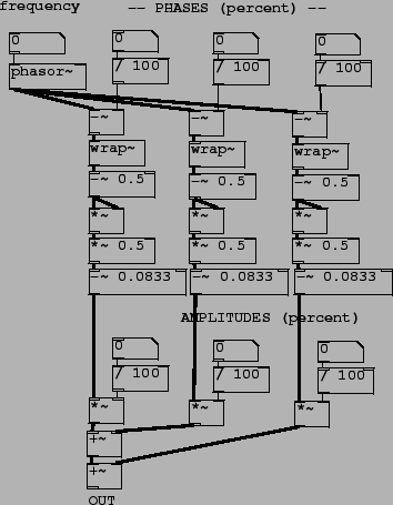
Patch J04.corners.pd (Figure 10.13 shows how to add parabolic waves to make a combined waveform with three corners. Each parabolic wave is computed from a sawtooth wave (ranging from -0.5 to 0.5) by squaring it, multiplying by 0.5, and subtracting the DC component of -1/12, or -0.08333. The patch combines three such parabolic waves with controllable amplitudes and phases. As long as the amplitudes sum to zero, the resulting waveform consists of line segments, whose corners are located according to the three phases and have slope changes according to the three amplitudes.
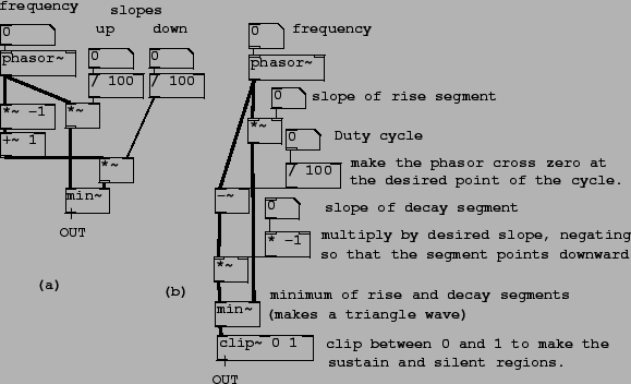 |
Patch J05.triangle.pd (Figure 10.14 part a) shows a simple way to make a triangle wave, in which only the slope of the rising and falling segment are specified. A phasor supplies the rising shape (its amplitude being the slope), and the same phasor, subtracted from one, gives the decaying shape. The minimum of the two linear functions follows the rising phasor up to the intersection of the two, and then follows the falling phasor back down to zero at the end of the cycle.
A triangle wave can be clipped above and below to make a trapezoidal wave, which can be used either as an audio-frequency pulse or, at a lower fundamental frequency, as a repeating ASR (attack/sustain/release) envelope. Patch J06.enveloping.pd (Figure 10.14 part b) demonstrates this. The same rising shape is used as in the previous example, and the falling shape differs only in that its phase is set so that it falls to zero at a controllable point (not necessarily at the end of the cycle as before). The clip~ object prevents it from rising above 1 (so that, if the intersection of the two segments is higher than one, we get a horizontal ``sustain" segment), and also from falling below zero, so that once the falling shape reaches zero, the output is zero for the rest of the cycle.
Patch J07.oversampling.pd shows how to use upsampling to reduce foldover when using a phasor~ object as an audio sawtooth wave. A subpatch, running at 16 times the base sample rate, contains the phasor~ object and a three-pole, three-zero Butterworth filter to reduce the amplitudes of partials above the Nyquist frequency of the parent patch (running at the original sample rate) so that the output won't fold over when it is downsampled at the outlet~ object. Patch J08.classicsynth.pd demonstrates using upsampled phasors as signal generators to make an imitation of a classic synthesizer doing subtractive synthesis.
Patch J09.bandlimited.pd shows how to use transition splicing as an alternative way to generate a sawtooth wave with controllable foldover. This has the advantage of being more direct (and usually less compute-intensive) than the upsampling method. On the other hand, this technique depends on using the reciprocal of the fundamental frequency as an audio signal in its own right (to control the amplitude of the sweeping signal that reads the transition table) and, in the same way as for the PAF technique of Chapter 6, care must be taken to avoid clicks if the fundamental frequency changes discontinuously.