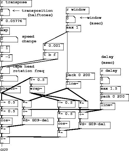
Patch G09.pitchshift.pd(Figure 7.33) shows a realization of the pitch shifter described in Section 7.9. A delay line (defined and written elsewhere in the patch) is read using two vd~ objects. The delay times vary between a minimum delay (provided as the ``delay" control) and the minimum plus a window size (the ``window" control.)
The desired pitch shift in half-tones (![]() ) is
first converted into a transposition factor
) is
first converted into a transposition factor
Once ![]() is calculated, the production of the two
phased sawtooth signals and the corresponding envelopes parallels
exactly that of Section 2.6.5 (the overlapping
sample looper). The minimum delay is added to each of the two
sawtooth signals to make delay inputs for the vd~ objects,
whose outputs are multiplied by the corresponding envelopes and
summed.
is calculated, the production of the two
phased sawtooth signals and the corresponding envelopes parallels
exactly that of Section 2.6.5 (the overlapping
sample looper). The minimum delay is added to each of the two
sawtooth signals to make delay inputs for the vd~ objects,
whose outputs are multiplied by the corresponding envelopes and
summed.