


Next: Butterworth filters Up: Designing
filters Previous: Band-pass filter
Contents Index
Peaking and band-stop filter
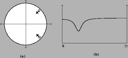
In the same way, a peaking filter is obtained from a shelving
filter by rotating the pole and the zero, and by providing a
conjugate pole and zero, as shown in Figure 8.16. If the desired center frequency is
 , and the radii of the pole and zero
(as for the shelving filter) are
, and the radii of the pole and zero
(as for the shelving filter) are  and
and  ,
then we place the the upper pole and zero at
,
then we place the the upper pole and zero at
As a special case, placing the zero on the unit circle gives a
band-stop filter; in this case the gain at the center frequency is
zero. This is analogous to the one-pole, one-zero high-pass filter
above.
Figure 8.16: A peaking
filter: (a) pole-zero diagram; (b) frequency response. Here the
filter is set to attenuate by 6 decibels at the center
frequency.
 |
Miller Puckette 2006-09-05