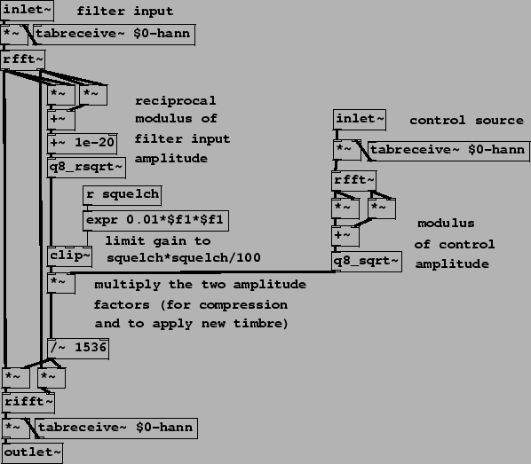
Example I05.compressor.pd (Figure 9.17) is another channel compander which is presented in preparation for Example I06.timbre.stamp.pd, which we will examine next. This is a realization of the timbre stamp of Figure 9.9, slightly modified.
There are two inputs, one at left to be filtered (and whose
Fourier transform is used for resynthesis after modifying the
magnitudes), and one at right which acts as a control source.
Roughly speaking, if the two magnitudes are ![]() for
the filter input and
for
the filter input and ![]() for the control source,
we just ``whiten" the filter input, multiplying by
for the control source,
we just ``whiten" the filter input, multiplying by ![]() , and then stamp the control magnitudes onto the result
by further multiplying by
, and then stamp the control magnitudes onto the result
by further multiplying by ![]() . In practice,
we must limit the gain to some reasonable maximum value. In this
patch this is done by limiting the whitening factor
. In practice,
we must limit the gain to some reasonable maximum value. In this
patch this is done by limiting the whitening factor ![]() to a specified maximum value using the clip~
object. The limit is controlled by the ``squelch" parameter, which
is squared and divided by 100 to map values from 0 to 100 to a
useful range.
to a specified maximum value using the clip~
object. The limit is controlled by the ``squelch" parameter, which
is squared and divided by 100 to map values from 0 to 100 to a
useful range.
Another possible scheme is to limit the gain after forming the
quotient ![]() . The gain limitation may in either
case be frequency dependent. It is also sometimes useful to raise
the gain to a power
. The gain limitation may in either
case be frequency dependent. It is also sometimes useful to raise
the gain to a power ![]() between 0 and 1; if 1, this
is a timbre stamp and if 0, it passes the filter input through
unchanged, and values in between give a smooth interpolation
between the two.
between 0 and 1; if 1, this
is a timbre stamp and if 0, it passes the filter input through
unchanged, and values in between give a smooth interpolation
between the two.