A compander is a tool that amplifies a signal with a variable gain, depending on the signal's measured amplitude. The term is a contraction of ``compressor" and ``expander". A compressor's gain decreases as the input level increases, so that the dynamic range, that is, the overall variation in signal level, is reduced. An expander does the reverse, increasing the dynamic range. Frequently the gain depends not only on the immediate signal level but on its history; for instance the rate of change might be limited or there might be a time delay.
By using Fourier analysis and resynthesis, we can do companding
individually on narrow-band channels. If ![]() is
one such band, we apply a gain
is
one such band, we apply a gain ![]() to it, to give
to it, to give
![]() . Although
. Although ![]() is a
complex number, the gain is a non-negative real number. In general
the gain could be a function not only of
is a
complex number, the gain is a non-negative real number. In general
the gain could be a function not only of ![]() but
also of any or all the previous samples in the channel:
but
also of any or all the previous samples in the channel: ![]() ,
, ![]() , and so on. Here we'll consider
the simplest situation where the gain is simply a function of the
magnitude of the current sample:
, and so on. Here we'll consider
the simplest situation where the gain is simply a function of the
magnitude of the current sample: ![]() .
.
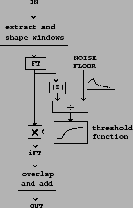
The patch diagrammed in Figure 9.8 shows
one very useful application of companding, called a noise gate. Here the gain ![]() depends on the channel amplitude
depends on the channel amplitude ![]() and
a noise floor which is a function
and
a noise floor which is a function ![]() of the
channel number
of the
channel number ![]() . For clarity we will apply the
frequency subscript
. For clarity we will apply the
frequency subscript ![]() to the gain, now written as
to the gain, now written as
![]() , and to the windowed Fourier
transform
, and to the windowed Fourier
transform
![]() . The gain is given
by:
. The gain is given
by:
In the figure, the gain is computed as a thresholding function
of the ratio
![]() of the signal
magnitude to the noise floor; the threshold is
of the signal
magnitude to the noise floor; the threshold is ![]() when
when ![]() and zero otherwise,
although other thresholding functions could easily be
substituted.
and zero otherwise,
although other thresholding functions could easily be
substituted.
This technique is useful for removing noise from a recorded
sound. We either measure or guess values of the noise floor
![]() . Because of the design of the gain
function
. Because of the design of the gain
function ![]() , only amplitudes which are above the
noise floor reach the output. Since this is done on narrow
frequency bands, it is sometimes possible to remove most of the
noise even while the signal itself, in the frequency ranges where
it is louder than the noise floor, is mostly preserved.
, only amplitudes which are above the
noise floor reach the output. Since this is done on narrow
frequency bands, it is sometimes possible to remove most of the
noise even while the signal itself, in the frequency ranges where
it is louder than the noise floor, is mostly preserved.
The technique is also useful as preparation before applying a non-linear operation, such as distortion, to a sound. It is often best to distort only the most salient frequencies of the sound. Subtracting the noise-gated sound from the original then gives a residual signal which can be passed through undistorted.