Chapter 2: Theory of operation
The purpose of this chapter is to describe Pd's design and how it is supposed to work. Practical details about how to obtain, install, and run Pd are described in the next chapter. Links to more extensive guides (and to more theoretical information about computer music) are provided in the previous chapter.
2.1. Overview
Pd (Pure Data) is a real-time graphical programming environment designed for audio processing, that can be extended for multimedia purposes and more. Pd resembles the MAX system, but is much simpler and more portable. For example, with Peter Brinkmann's libpd, you can use Pd as an embeddable audio synthesis library. Additionally, Pd was originally designed to offer a unique experimental feature not found in MAX, allowing users to define and access data structures in innovative ways, with the ability to attach shapes and colors to data in order to visualize it and/or edit it graphically (see section 2.10 Data Structures for details).
Despite its lightweight and portable nature, Pd offers a wide range of external packages that enhance its capabilities, primarily focusing on audio and control processing, but also for graphical processing and whatnot. For examples and details on installing and managing packages, refer to Chapter 4: Externals.
2.1.1. The main window, canvases, and printout
Pd starts with the main "Pd" window. When you open a Pd document file you'll see a
separate window, known in Pd as a canvas and also referred to as patch.
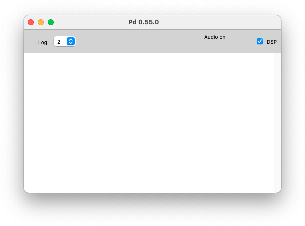
The main Pd window looks like this:
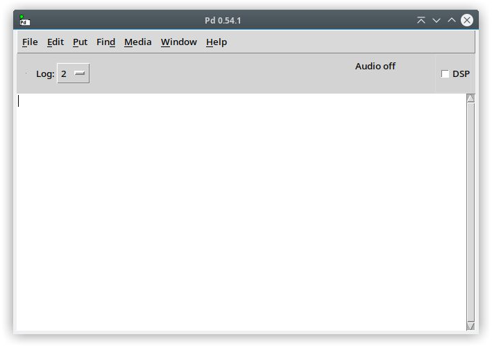
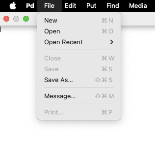
At the top, you'll see the menu entries: File, Edit, Put,
Find, Media, Window and Help (on Macs, this is shown
at a top bar on the screen, and there is an additional first Pd menu entry similarly
to other apps on macOS and as seen below). You can create and open patches via the
File menu, where you can also close and save them (note the handy shortcuts).
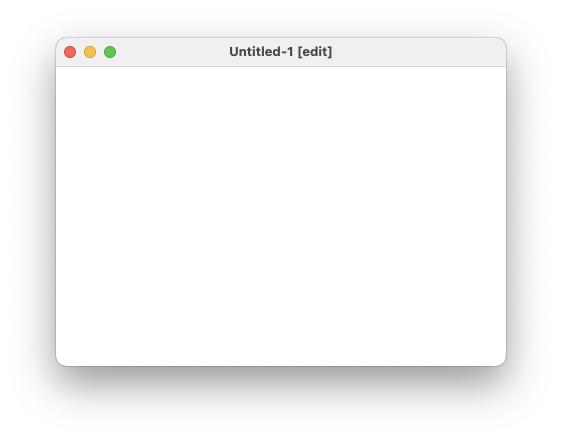
Creating a new file creates a blank window.
The lower part of the Pd window is a console area for printout from outputs of
boxes in patches and for messages from Pd itself. Here is a simple Pd patch:
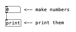
This patch contains four text boxes: a number box (displaying "0"),
an object box labeled "print", plus two comments (which are simply texts
that don't affect the patch and can't be connected to anything). The number
box is connected to the object box, with the output of the number box feeding into
the input of the [print] object box. Boxes may have zero or more inputs
and/or outputs, called inlets and outlets. Inlets are visible at the top of objects
and outlets at their bottom. When clicking and dragging on the number box in run mode, the values
are printed in the main "Pd" window.
On the upper right of the main Pd window, there is a DSP toggle, which stands
for "Digital Signal Processing" and turns audio processing on and off globally. DSP
is off by default when Pd is opened. When you turn it on, Pd starts computing
audio samples in realtime for all open patches (whether they are visible or not).
Turning off DSP halts the computation and releases any audio devices that Pure Data is utilizing. You can configure audio devices as described in 3.3.1. Audio settings.
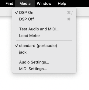
The Media menu offers shortcuts to toggle DSP on and off. Use Ctrl+/
("Control" key on PCs or "Command" key on Apple computers plus the / key)
to turn audio processing on, and Ctrl+. to turn it off. You can check the input
audio level if you select "Test Audio and MIDI..." and make other Audio and MIDI tests (read more
about this in 3.3. Testing and configuring Audio and MIDI).
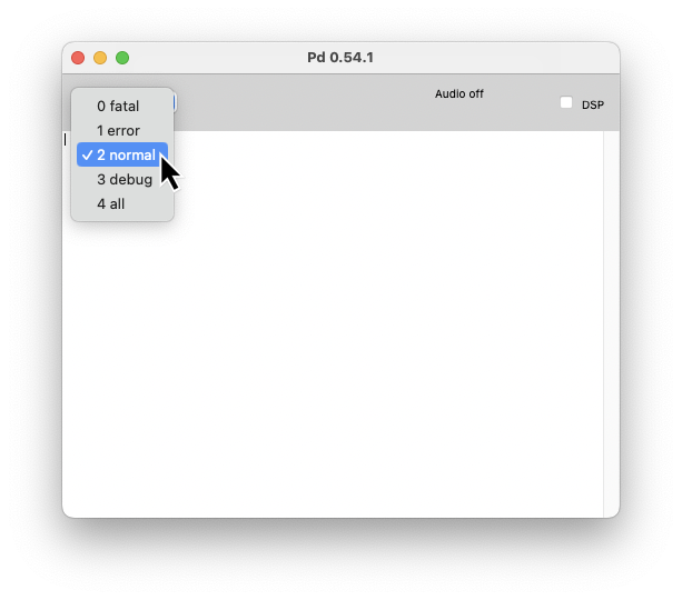
Besides printing the messages from objects, the Pd window logs several messages from Pd.
You can set different log levels to filter the output. The default level is 2 (normal).
You can increase it to get more detailed information or decrease it to only see fatal errors.
Errors are mostly printed by objects and displayed in the Pd window in red color. You can find error sources for the corresponding line with Ctrl+click as shown in here).
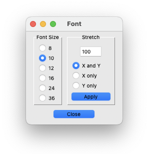
If the Pd window is focused, the font size for menus and printout can be changed
using the "Font" dialog entry in the Edit menu.
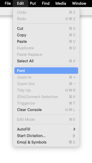
Make your adjustments in the Font dialog window and increase the size if you are
having trouble reading on HiDPI screens. You can ignore the "Stretch" parameter here, since
that only works for Pd documents.
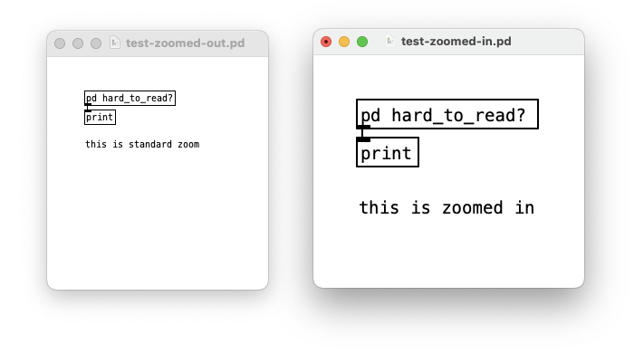
Pd documents (called "patches" or "canvases") have their own main window and any number of sub-windows. The sub-windows can be opened and closed, but they are always running, whether you see them or not. When opened, sub-windows show up as a separate canvases. When you have a patch window focused, you can use the "Font" dialog entry in the Edit menu to set the patch's font size, which also applies to its subwindows. Note that the patch's font size gets saved with the file.
For patch canvases, you can also use the "Stretch" feature, which stretches or compresses text elements (boxes) of your patch. This can be used to realign objects accordingly to font size changes which don't affect the layout.
In the Edit menu you can also Zoom In and Zoom Out a patch window.
Note that the Zoom setting is not saved in the patch though.
In the Edit menu, you can also clear all messages printed in the Pd window with the "Clear Console" entry (shortcut Shift+Ctrl+L). On the Window menu, you find the "Pd Window" entry (shortcut Ctrl+R), which brings the Pd window to the front or sends it behind the last focused patch.
On PCs, this menu shows the Ctrl+Q entry to quit Pd, which prompts you to confirm the action (on Macs, this is listed in the Pd menu). To quit without confirmation, you can use Shift+Ctrl+Q.
2.1.2. Object boxes
The object box loads an instance of a class in your patch. You can create an
object box from the Put menu. When you insert a new object box, it is empty
and presented with a dashed border before creation.

You only create a particular object after you entered text into the
object box and click outside it to instantiate it. The text consists of atoms,
which are separated by spaces. The first atom (which needs to be a symbol) determines
the type of object Pd will create, while the subsequent atoms, known as creation
arguments, instruct Pd how to initialize the object. For instance, you can type
"+ 13".

Here, the "+" specifies the class of the object. In this case the object will carry out additions, and the "13" initializes the value to add.
Atoms are either numbers or symbols. Anything that is not a valid number is considered a symbol. Valid numbers may or may not have a decimal point, such as "12", "15.6", "-0.456". Numbers in Pd may also be written in exponential notation and have limited display and internal precison. Check more details in subsection 2.4.1..
A number that starts with a "+" is not considered a valid number and is considered a symbol instead, so is "0..6" as well as words and names such as "Zack" or "cat". The symbols "gore", "Gore", and "GORE" are all distinct, reflecting case sensitivity.
The text you type into an object box determines how many and what kinds of inlets and outlets the object will have. Certain classes, such as [+], consistently maintain a fixed configuration of inlets and outlets. However, for other classes, the number and arrangement of inlets and outlets can vary based on the creation arguments.
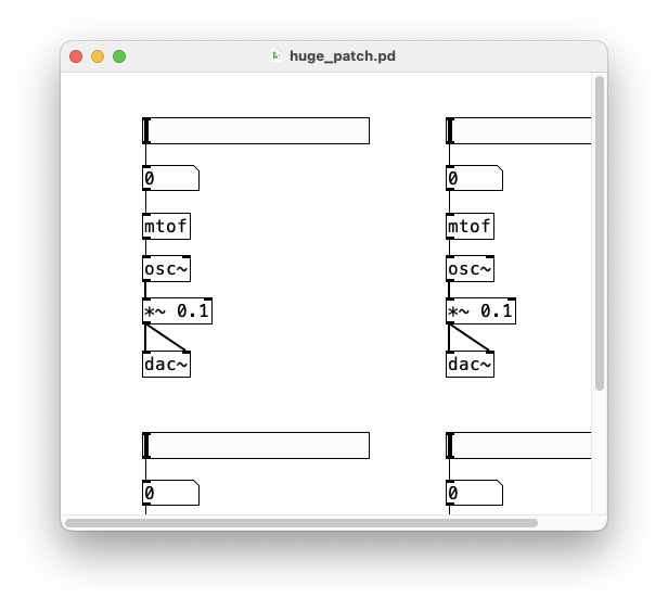
Here is an example of a simple synthesizer that takes a MIDI input and
synthesizes a pure tone:
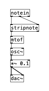
This patch mixes control objects ([notein], [stripnote], and [ftom]) with tilde objects ([osc~], [*~], and [dac~]). These are the two types of objects that exist in Pd: control objects and signal objects.
The control objects on the upper half carry out their function sporadically, as a result of one or more types of events. In this case, incoming MIDI note messages set off the control computation. When a note event happens (more specifically a "note on" event, since "note off" events are filtered by [stripnote]), the control computation is triggered and it computes the frequency in cycles per second with [mtof] and passes it on to the oscillator ([osc~]).
The objects in the lower half of the patch ([osc~], [*~], and [dac~]) compute audio samples. The [osc~] object serves as the interface between the two regimes; it takes control messages to set its frequency but outputs an audio sine wave to a gain level adjustment in [*~], which then goes to the output via [dac~].
The connections in the patch (the lines between the boxes) are also of the types "control" or "signal". Note that they are visually distinct, where signal connections are thicker than control connections. The connection type depends on the outlet it comes from.
It's possible to make control connections to a signal inlet; if numbers get sent through it, they are usually automatically converted to signals. Signal connections can't be made to control inlets though; some sort of explicit conversion from audio signal to control data is necessary in this case.
Audio signals form continuous streams of numbers, not intermittent bursts. Therefore, tilde objects operate under rules distinct from those of control objects. When DSP is activated, the audio segment of the patch runs continuously, regardless of whether MIDI messages are received. In contrast, control computations are interspersed within the audio processing, allowing for the adjustment of parameters such as the frequency of an oscillator in this example.
2.1.3. Message and GUI boxes
The shape of a box tells you how its text is interpreted and how the box functions. Object boxes (as in the previous example) are rectangular and use the text to create objects when you load a patch or type text onto a new one. That is, the contents of an object box describe a message which is sent to Pd to create the object. If you retype the text in an object box, the old one is discarded and a new one is created, using the new creation arguments.
Message boxes have a different shape and interpret the text as a
message to send whenever the box is activated (through an incoming message or via
a mouse click). The message may be sent many times while the patch is running
(as opposed to object boxes whose message is used once to create the object).
Instead of going straight to Pd, the message box's messages go either
to its outlet or to other receiving objects specified in the message itself.
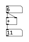
In the example below, a click on the message box sends the message "21" to the
connected object box, which adds 13 to it.
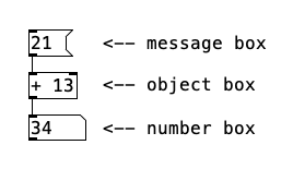
The third box here is a GUI ("graphical user interface") box. Pd has 3 basic GUI boxes. In addition to number boxes (as in this example), there are symbol boxes to display and edit symbols and list boxes for arbitrary lists of atoms.
Pd also comes with another set of GUIs that include bang, toggle, sliders, radio buttons, etc.
You can interact with GUIs in many ways and they are visually dynamic. For instance, while the appearance of an object or message box remains unchanged when a patch is running, a number box's content changes to reflect the current value held by the box. You can also use a number box as a control by clicking and dragging up and down, or by typing values in it and hitting enter (more details on how this and any other GUIs work is available in the objects' help files; see 2.2.7. Popup menu for "Properties", "Open" and "Help".
2.1.4. Patches and files
As mentioned before, you can create or open Pd files from the File menu, as well as close and save them.
When you save a patch to a file, Pd doesn't save the entire state of all the objects in the patch, but only what you see: the objects' creation arguments and their interconnections. Nonetheless, the [savestate] object offers a mechanism to save the state of abstractions (see 2.8. Subpatches). Also, certain data-storage objects have functions for reading and writing files to save and restore their internal state (one example is the [text] object). When loading a patch, the [loadbang] object can be used to initialize the parameters of your patch, so you can load text files and make other preparations.
Pd searches for files using specified paths. Most objects capable of reading files search along these paths, but when Pd writes files, they are saved to the directory where the patch itself is located by default. Check 3.4. Path and startup for more details.
2.2. Editing Pd patches
Normally, you'll use Pd in run mode, which is also referred to as "performance mode". In order to edit a patch, you need to go into edit mode.
2.2.1. Edit and run mode
When you open a Pd file, it is in run mode. In run mode, the cursor is an arrow that
points up and is slightly tilted to the left, but it points straight up when you are
able to click on a box. In run mode, you mostly click and interact with GUIs (like the
number box) and message boxes (which are used as controls to send messages).
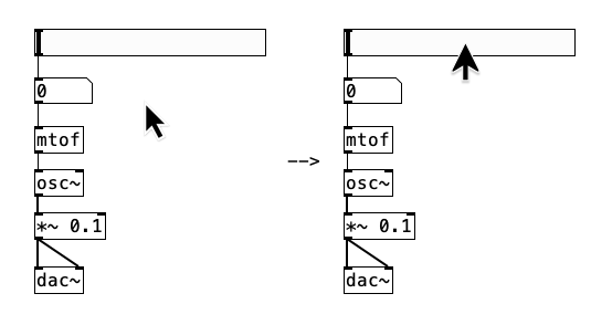
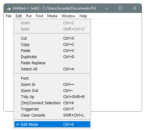
In order to go into edit mode, you need to select the "Edit Mode" entry from the
Edit menu to activate and check it on.
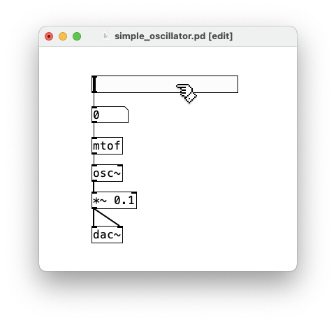
When you are in edit mode, the patch actually runs in the same way as in run mode,
processing control data and sound (if DSP is on), but you're able to edit the patch
while it runs. The only real change is how mouse clicks affect the patch. In run mode,
mouse clicks will interact with the patch and change parameters of the performance, while
in edit mode the purpose of mouse clicks is to edit and change the patch. Note that in
edit mode, the mouse cursor becomes a pointing hand instead of an arrow. Unchecking the
"Edit Mode" entry returns the patch to run mode and changes the cursor back to an
arrow. You can use the Ctrl+E shortcut to switch between these modes.
In edit mode, you can move boxes around by clicking on them and dragging.
You can also edit text, create or delete boxes and make or cut connections (more
details on this will follow below) and you can resize some boxes in your patch,
namely object boxes, number/symbol/list boxes, comments, messages. Note you can
also resize Graph-on-parent subpatches and
Arrays.
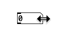
You need to move the cursor to the right edge of the object and you'll see the cursor becoming a double-sided horizontal arrow. You can then click and drag horizontally to resize these box. IEMguis do not offer this feature yet and other externals may offer this or custom possibilities for resizing.
If you are predominantly editing a patch, but would like to quickly switch to run mode just to click on something like a message, you can press and hold the Ctrl to temporarily switch to edit mode until you release it.
In the Edit menu you also find "Undo" and "Redo" operations, which revert and recreate changes you've done in your patch while in edit mode. Note that you can also "Undo" and "Redo" while in run mode.
You can resize patch windows like any other windows in your OS. Note that the mouse
becomes a double sided arrows in the horizontal and vertical edges or corner bounds.
This is possible regardless if you are in edit or run mode. If boxes are outside
the visible area, you'll see that scrollbars appear. In both edit or run mode you can
navigate through the hidden area. Besides dragging the scrollbars, you can pan the patch
vertically by turning the mousewheel and horizontally when pressing and holding
Shift while doing so. On trackpads, you can use 2-finger scrub gestures to
pan in all directions. Resizing the patch window to fit all objects in removes the
scrollbars.
2.2.2. Creating boxes
Pd patches can have four types of boxes: object, message, GUI and
comment (which counts as a "box type" even though it's not a "box" visually).
You can create these boxes using the Put menu. Also note the handy shortcuts
to create each item specifically.
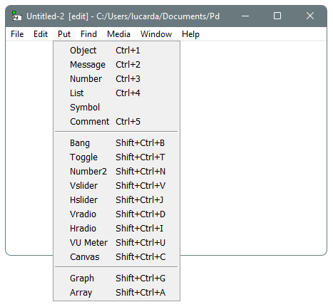
Note that most of these are individual GUI (graphical user interface) boxes. Besides the three basic GUI boxes (number, symbol and list), there's another group of GUIs that has more options (toggles, sliders, radio buttons, etc). These other GUIs are also known as "IEMguis", which used to be an external library package and was incorporated natively into Pd in version 0.34 (they can still be created from object boxes though - see their help patches for the corresponding symbols). There are also entries for "array" and "graph" that will be explained later.
If you are in run mode and click on an entry in the Put menu or use a shortcut, Pd automatically switches to edit mode. When you add boxes this way, they are automatically selected and follow the mouse cursor; drag them around as desired until you click to position them where you want. The box will still be selected and you can input text.
Message and object boxes are empty when added. Typing into them will also force position the boxes if they haven't been positioned yet by a click. To actually create the object, deselect it by clicking on an empty spot of the patch or using the Esc key.
When you add a comment box, it shows a "comment" placeholder text. When you position it, the text is selected and you can start typing a new commentary. Similar to an object box, the comment is only created after deselecting it. Same is true for a message box as the message is only part of the patch after deselecting it. Saving a patch without properly created objects, comments or message boxes will save them as empty boxes.
You may find it more convenient to select a box and "duplicate" it than to use the Put menu. If you duplicate a selection of several items, connections between them will be duplicated as well. To deselect more than one box, you can also either click on an empty area of your patch or press Esc.
2.2.3. Selecting items and moving them or "tidying them up"
In Edit mode you can select or deselect one or more boxes. Note that the outline of all boxes and containing text turn light blue (instead of the usual black) to indicate they are selected. Boxes in a Pd window may be individually selected by clicking on them. If you don't release the mouse button you can select a box and drag it around right away.
To select more than one box, you may use Shift+Click on each item. You can then click again on one of the selected boxes to move the group around. Alternatively, you click on a blank portion of the window and drag the cursor to select all boxes within a rectangular area (then click again on one of the selected boxes to move them as well). If you press Shift, you can repeat the click and drag operation to select another group of boxes as well. If you do Shift+Click on a selected box, you deselect it. The "Select All" entry on the Edit menu (Ctrl+A) selects all items in a patch window.
When you have one or more boxes selected, you can also move them by using the Arrow keys, which moves items one pixel in the direction of the arrows. You can also use Shift+Arrow keys to move items 10 pixels in the desired direction. By the way, if you select boxes that are connected, the connections (patch cords) are also moved around.
The "Tidy Up" entry in the Edit menu allows you to align
selected boxes that are not perfectly aligned. You can select boxes arranged in a
horizontal row and use the shortcut Shift+Ctrl+R
to try and align them perfectly horizontally. Similarly, this can be applied to
vertically align a column of boxes. Bidimensional rectangular selections of boxes
are also possible, but aligning horizontally and vertically separately tends to yield
better results. When boxes are misaligned drastically, this action won't do anything.
2.2.4. Delete, cut, copy and paste boxes
If you select any item you can press Backspace or Delete key to delete it. Connections of a deleted box are also deleted. A multiple selection of items (and their connections) can also be deleted.
For one or more selected items and their connections you can also "Cut", "Copy", "Paste" and "Duplicate" from the Edit menu or shortcuts. Note that you can "Cut" or "Copy" and then "Paste" the selection in a different patch window. When pasted, the items stay selected, so you can click on one of them and move the whole selection around by dragging (or move them using the arrow keys).
You'll see that pasting inserts the selection at the same position it was copied from, unless the place is already taken; in that case, there is a small offset. The "Duplicate" menu entry performs a copy and paste with a similar offset (since the original selection remains in the original position).
Note that the cut/copy/paste functionality for patch elements is not integrated with the operating system's clipboard. This limitation prevents you from pasting between different versions or flavors of Pure Data. Furthermore, it is not possible to copy from a patch and paste into a Pd subprocess that was instantiated through a [pd~] object.
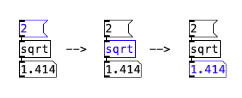
2.2.5. Changing the text of objects, messages and comments
Clicking on an unselected object, message or comment box and releasing the click makes the text active, i.e., ready to be text edited (if you select using a rectangular area selection or Shift+Click, the text isn't activated).
If you only click once, the entire text is selected and your typing will replace the whole selections. Use Arrow keys to navigate the cursor through the text or use the mouse to click and drag to change the text selection and edit it.
If you wish to displace a box whose text is activated you need to first deselect it (by clicking outside it or using Esc), otherwise you will be selecting text instead of moving the box.
The updated text only becomes part of the patch when you deselect the
object. As already mentioned, changing the text in an object box deletes
the old object and creates a new one; so the internal state of the old one
is completely lost.
You can also use the copy, cut, and paste commands for the selected text. The text selection functionality for cut/copy/paste is integrated with the operating system, enabling you to copy and paste text between Pd and other software applications.
2.2.6. Connecting and disconnecting boxes
This subsection only describes the simplest way to connect two boxes. For more advanced and convenient techniques and shortcuts, refer to the next section.
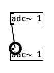
To create a connection in edit mode, move your mouse into the the area of
an outlet. Note that the cursor becomes a circle (a patch point), indicating
that you can click and drag to create a connection. Drag the cord into an inlet
area, where you'll see again the circle shaped cursor, signaling that you can
release the mouse button to create a connection. You can release the mouse button
anywhere within the target box and the connection will be made to the nearest
inlet.
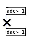
If you move the mouse cursor over a patch cord, you'll see it takes the shape
of an "X" to denote you can select it and delete it. Click on the connection
to select it and press Backspace or Delete key to delete
it. You can't just select patch cords with click and drag for a rectangular
area and you can only select a single connection by clicking on it.
2.2.7. Context menu for "Properties", "Open" and "Help"
All the "clicking" mentioned above is done with the left mouse button. The right button, instead, opens a context menu offering "Properties", "Open" and "Help" (either in edit or run mode). Apple users, who may only have one button should know that Control+Click is mapped to right-click and that new magic mouse devices can map gestures when you click with two fingers (same is true for trackpads).
Selecting "Help" on any box opens a patch explaining and demonstrating what it is and how it works. Asking "Help" for the canvas as a whole (right-clicking outside any box) gives a list of all built-in boxes and every object class.
The "Open" menu item is only enabled if you right-click on a subpatch and prompts Pd to open it. Ordinary subpatches may also be opened by simply clicking on them, but for graph-on-parent subpatches this is the only method available.
The "Properties" dialog allows you to change certain settings of GUI boxes or of the patch itself (when clicking outside any box).
2.3. Advanced patch editing
This section describes advanced techniques and shortcuts for editing patches.
2.3.1. Tab navigation
When a single box is selected, pressing Tab allows you to
navigate and change the selection to other boxes in the sequence determined
by the order of their creation. Pressing Tab cycles through the
boxes from the earliest created to the next, and upon reaching the last box
in the window the selection loops back to the first one. Conversely, you can
press Shift+Tab to navigate in reverse order, moving from the
most recently created box back towards the first created ones.
Using Tab also works in a similar way for patch cords if
you have one selected. You can move from first to last with Tab
and from last to first with Shift+Tab.
If you're creating a connection by clicking on an outlet and dragging a
patch cord, you can also use Tab to cycle through outlets.
The navigation order is left to right and it also cycles back. Pressing
Shift+Tab navigates from right to left.
In Linux and Windows you can also cycle between inlets. This is currently not possible on macOS. When dragging a connection into an inlet area, without releasing the mouse, you can use Tab to navigate to the next inlet, or Shift+Tab to navigate to the previous one.
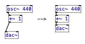
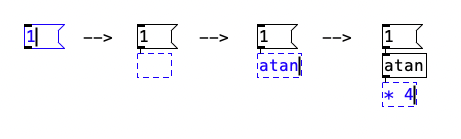
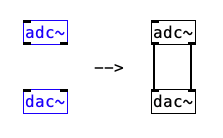
2.3.2. Autopatching
By default, Pd has an "autopatching" mode set to on. You can disable it via startup flags (see "-autopatch" flag 3.4.1. Startup flags). This works with the shortcuts from the Put menu for inserting boxes. If you have a selected box and use a shortcut to create another one (such as Ctrl+1 to create an object box), the created box is placed below the selected box and a connection is made from the first outlet of the selected box into the inlet of the newly created box (granted that these boxes have an outlet and an inlet for the connection to happen).
Once the new box is created, it is also selected, so you can continue with
autopatching by adding yet more boxes. In the case of object and message boxes
you can also start typing text into it before autopatching into another newly
created box, since when you autopatch for the next one, the object or message
box gets deselected and instantiated.
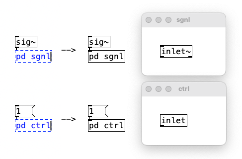
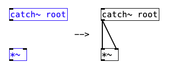
You can also autopatch into a newly created subpatch (see
2.8. Subpatches). By creating an object box and typing "pd", as soon as you
deselect the object, a [pd] subpatch is created with an
inlet - either a control [inlet] if the object
above is a control object, or a signal [inlet~] if
it is a tilde object instead.
2.3.3. Duplicate connections
If you select a connection between two boxes that have more than one
outlet and inlet for connections, you can use Ctrl+D to
duplicate and create more connections.
2.3.4. Managing connections with the shift key
You can swap connections if you selected a connection and use
Shift+Click on another one.
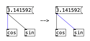
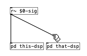
You can "fan out" connections when no boxes are selected. You can
start creating a connection by clicking an outlet and dragging a cord
and then use Shift when you reach the inlet destination
(without releasing the mouse button). This "fans out" out and creates
another connection from the outlet for you to drag somewhere else and
connect the same outlet to to multiple inlets sequentially.
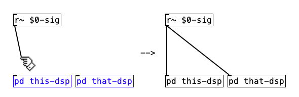
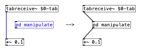
Also for fanning out, if you have a group of target boxes that are selected,
you can drag a cord from an outlet of an unselected box and press Shift
to create a connection into the same inlet number of the selected boxes (which do
not need to be of the same type or class).
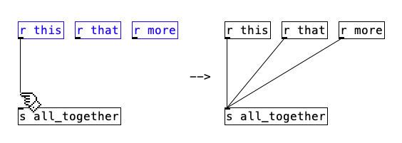
You can create a connection from the same outlet number of multiple boxes to
a single inlet. If you have a selection of source boxes, you can drag a cord from
one of their outlets into another box and press Shift to create multiple
connections from the same outlet number of the selected boxes (which do not need to
be of the same type or class).
You can connect multiple outlets and inlets of 2 boxes if you have 2 selected
boxes. Start creating a connection and click Shift at completion.
This creates all possible connections starting from the chosen outlet and inlet.
You can connect outlets of multiple boxes into multiple inlets of one box.
If there's a selected group of boxes, you start creating a connection into an
inlet of a box that is part of the selection. Then you can press Shift
so connections are made from the same outlet number of all source boxes (which do
not need to be of the same type or class) into separate inlets, starting from the
chosen inlet.
You can spread multiple outlets of one box into same inlets of other boxes.
Similarly to the scenario above, you can start dragging from one outlet of a
selected box with multiple outlets to an inlet of one of many selected boxes.
In this case, when you press Shift, all possible connections are
made from the outlets of the source box to the same inlet numbers of the target
boxes.
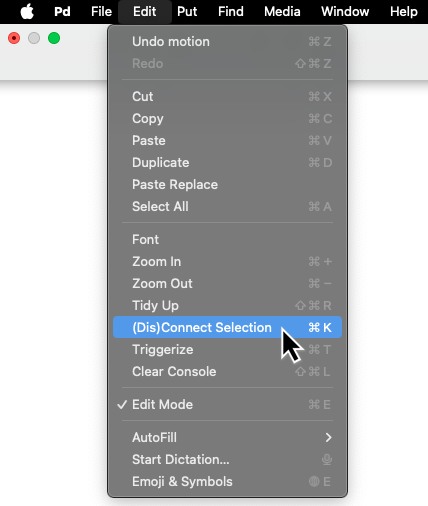
2.3.5. (Dis)Connect selection
This is a menu entry in the Edit menu, also available via the shortcut
Ctrl+K. It allows you to connect and disconnect selected
boxes in different ways.
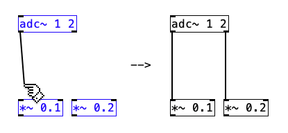
For 2 selected boxes you can use Ctrl+K to connect
them. Repeat using Ctrl+K to make multiple connections
from possible remaining outlets to inlets.
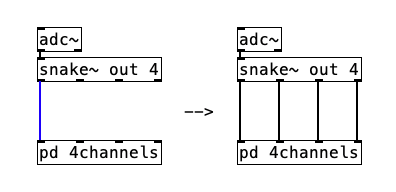
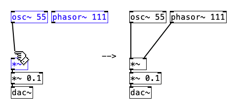
For 2 selected tilde objects, if the origin object has a single outlet and
the target object has many inlets, you can repeatedly use Ctrl+K
to fan out and connect the same outlet to all inlets.
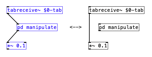
For last, you can include or bypass a box into or from a connection
(being it any connection from any outlet into any inlet). To include a box,
you can select it and the connection between the other 2 boxes by using
Shift+Click and then use Ctrl+K to include
the selected box into the connection. Alternatively, you can select the 3
boxes with a connection between 2 of them and then use Shift+Click
to include the third one in the connection.
To bypass a box, you can select 3 boxes connected in a row and use
Ctrl+K to bypass and remove the middle box from the connection.
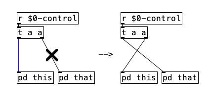
2.3.6. Triggerize
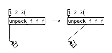
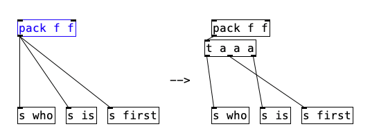
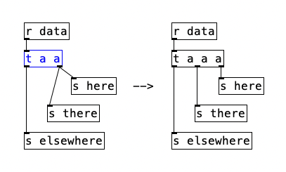
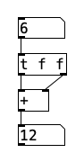
The "Triggerize" entry in the Edit menu (with the Ctrl+T shortcut) was designed to insert a [trigger] object (in its abbreviated form [t]) into your patch. Start by selecting a single box that is connected to many inlets (of one or more boxes), then use "Triggerize" to insert a [trigger] object after the selected object.
The [trigger] object is widely used in Pd to control the order of execution from right to left and is briefly described in 2.4.3. Hot and cold inlets and right to left outlet order. "Triggerize" then creates the [trigger] object taking into account the order in which the connections were made, where the first connection starts at the rightmost outlet of [trigger] and continues to the leftmost.
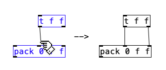
In the example below, a [pack] object is selected and connected
to three [s] ([send]) objects. Triggerize
then introduces [t a a a] (short for
[trigger anything anything anything]) with three outlets and the
order that the connections from [pack] were made reflect the order
from right to left. You can swap connections with the Shift key (as described
in subsection 2.3.4.) if you need to adjust the order of
connections.
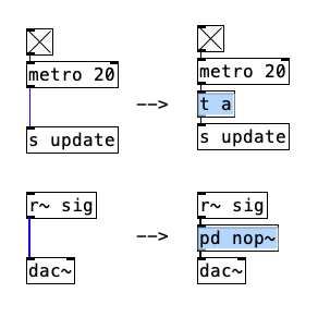
Additionally, the "Triggerize" option can be used to insert a dummy object. To do so,
select a connection and use Ctrl+T. For a control connection, a
[t a] object is created with the text selected, so you can type
new text to create another object instead. Similarly, for a signal connection, a
[pd nop~] ("no operation") subpatch is created.
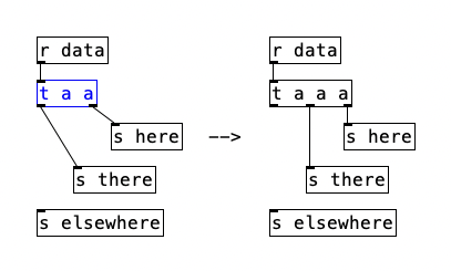
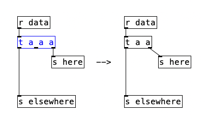
Triggerize also allows you to create or remove outlets of a selected
[trigger] object. The result depends on the existing connections
and outlets. As shown below, if each outlet has a single connection, it will insert an
outlet on the left.
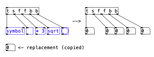
2.3.7. Paste replace
The "Paste Replace" entry in the Edit menu doesn't have a shortcut and performs
a special paste operation where it replaces a selection of boxes for another kind. For
example, first copy one box such as a [float] object. Then select
a group of boxes of the same type, for instance, a group of object boxes (note that they
don't need to be of the same class). Now go to the Edit menu and select "Paste
Replace". All the selected boxes of the same type get replaced by the copied box and
connections are preserved.

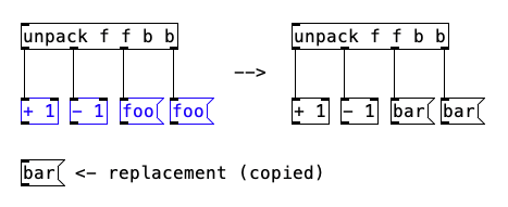
Alternatively, you can copy a number box instead of a [float] object
and replace it in the selected group of objects, or in a selected group
of another kind, such as message boxes. Note that the box types in Pd
are: objects, messages, GUIs and comments, whereas IEMguis are actually
treated as regular object boxes in this case. Hence, the GUI boxes are
only the number box, the symbol box and the list box. Also note that
these three GUIs are not of the same kind for the purpose of "Paste Replace".
A subpatch or an abstraction can also be used for "Paste Replace" and they
count as the same object group type.
If you have a selection of boxes to replace that includes different
types of boxes, the "Paste Replace" will only replace the boxes of the
same type that was copied.
2.4. Messages
In Pd, boxes intercommunicate by sending messages and/or audio signals. Pd messages are sporadic, like MIDI messages or Music N "Note cards". The management of messages in Pd corresponds to the "control" realm, as opposed to audio signals, described in the next section.
2.4.1. Message types (selectors) and numerical precision
Messages contain a selector followed by any number of arguments. The selector
is a symbol that defines the message type. The arguments are anything that follows and
may be symbols or numbers (aka atoms). For instance "list a b c" has a "list"
selector, which defines the "list" data type, and "a b c" is the actual message. This
message is only composed of symbols but a list message can combine two or more
symbols and/or floats.
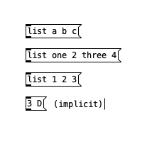
Above, we see some variations of list messages. Note that when you have messages with two or more elements that start with a number, the list selector is not necessary: if you don't specify it, Pd will implicitly interpret it as a list message. Hence, numbers cannot be used as selectors. While a message with a number followed by other arguments is automatically given the "list" selector, a single number message is automatically given the "float" selector.
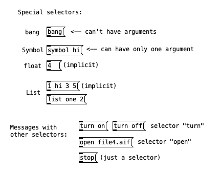
There are common, or special, selectors that Pd defines, so that objects can
be connected with maximum flexibility. These special types are: "float",
"symbol", "list", "bang" and "pointer" (the latter one only
used for data structures). Other message selectors can be any other symbols. If a message
contains only one symbol, like "stop", it is considered a selector with no actual message
(i.e., no arguments) attached. The bang message is a special selector and takes no
arguments. The symbol selector can only have one symbol argument. See below.
When a message is passed to something (which is commonly an inlet of a box, but could
be anything that can receive a message), the selector of the message is checked against
the receiver. If the receiver recognizes messages of that selector, it carries out some
corresponding action. Let's take the [float] object below as an example.
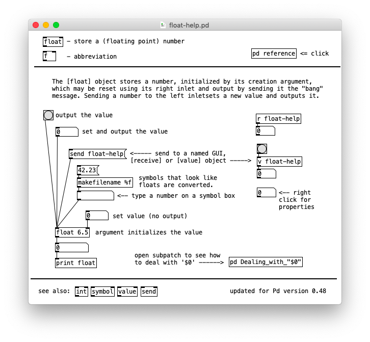
Note that the [float] object has two rectangles at the top, called
inlets, where the one on the left directs incoming messages to the [float]
object itself, while the one on the right directs messages to an auxiliary "inlet"
object. The [float] object itself (represented by the left inlet) accepts messages
with the selectors "float", "bang", "symbol" and "send". The right inlet only accepts
messages with the "float" selector. Out of the special selectors, only "list" is not
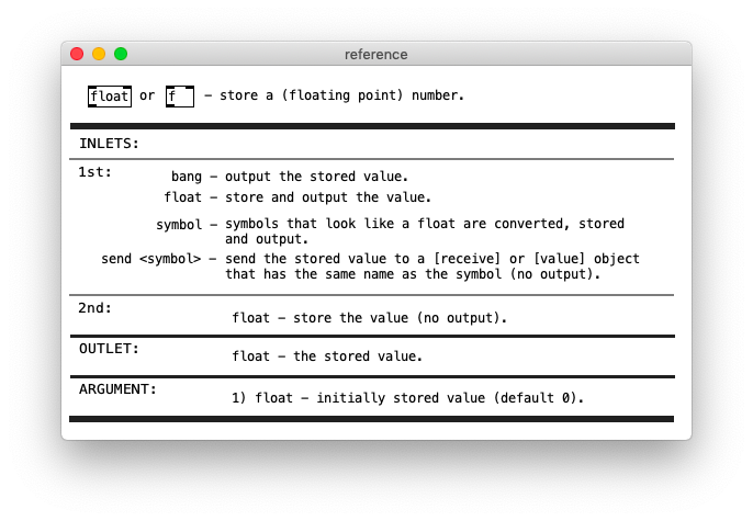
accepted. The help files of objects have a "reference" subpatch with detailed
explanations for the funcions of all inlets and outlets, also specifying what kind
of messages they take and output. See below.
Actual messages are composed of 'atoms' (numbers or symbols). As mentioned above, there is an extra pointer type used for data structures, which you cannot see or type on the patch level though. So all you can actually see in boxes and printed in the console log are numbers and symbols. As mentioned earlier, all that is not considered a number is interpreted in Pd as a symbol. Hence, symbols can contain and start with decimal digits.
Number atoms are always of type float, meaning that Pd does not have an integer number type. Numbers in Pd may also be written in exponential notation, such as "4.5e+06", which means 4.5*106, resulting in 4'500'000. Negative exponents also work, such as 1.5e-06, which means 1.5*10−6 and results in 0.0000015.
Depending on their value, numbers are displayed either in decimal or exponential notation. You'll only see up to three zeros after the decimal point before the first non-zero digit. For instance, "0.0001". If you add another zero, Pd turns it into exponential notation for display, so "0.00001" becomes "1e-05". Conversely, if you type "1e-04", Pd converts it to "0.0001" for display.
Other than this, Pd only displays 6 significant digits. This means that you can have "100000", but adding another zero will switch the representation to "1e+06". Similarly, typing "1e+05" results in "100000".
Having 6 significant digits means that numbers are rounded. You can display "0.000123456", which has 6 significant digits, but adding another digit as in "0.0001234567" forces Pd to round it to "0.000123457". Now, adding another zero before the first significant digit turns this into exponential notation as "1.23456e-05", keeping the display of the 6 significant digits. Similarly to the earlier example, "1.234567e-05" becomes "1.23457e-05". The 7th significant digit is rounded in a way that "0.9999994" or less becomes "0.999999" and "0.9999995" or higher becomes "1".
Don't mistake the display precision and rounding with the actual floating point precision though. If compiled for single precision, numbers in Pd are handled as 32-bit floats, which allows you to represent any integer with 7 digits or less, even though Pd will only display 6.
Note that the display resolution remains the same when Pure Data is compiled for double
precision, even though the resolution is much higher in Pd64. Since Pure Data has no
integer data type, the range of representable integer numbers depends on the float
precision. The integer range is shown below for single and double precision.
Pd
Pd64
32-bit floating point
64-bit floating point
min integer
−224 (−16777216)
−253 (−007199254740992)
max integer
224 (16777216)
253 (9007199254740992)
Hence, there is a discrepancy in what Pd displays and what the actual number
is. In some cases you may not want to represent floats in a message or object as
it is prone to rounding errors. For instance, Pd can only represent Pi as
"3.14159", but it can be calculated with more precision from math objects.
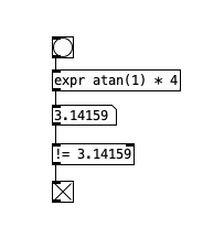
In the picture above, the [expr] object takes a bang and calculates the value of pi. The number box displays "3.14159", with 6 significant digits, but internally the precision is higher. We then compare the output of the number box with [!=] ('not equal' object) to see if it differs from the number we can type in Pd with the possible display resolution of the number Pi. The [!=] object then outputs "1" and activates the toggle, which shows that they are not really the same number.
Note that while typing a number into a message or comment, Pd can display it with more precision or even with a different notation (decimal instead of exponential), but copying and pasting it or saving and reopening the patch forces rounding.
2.4.2. Depth first message passing
Whenever a message is triggered in Pd, the receiver may then send out
further messages in turn, and the receivers of those messages can send yet
others. So each message sets off a tree of subsequent messages. This tree is
executed in depth first fashion. For instance in the patch below:
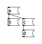
The order of arrival of messages is either A-B-C-D or A-C-D-B. The "C" message is not done until the "D" one is also, and the "A" is not done until all four are. It is not visible whether "B" or "C" is done first; this depends on the order the connections were made in.
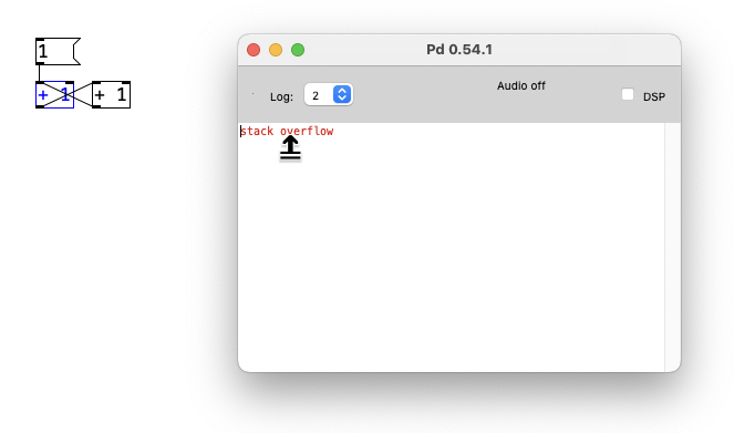
Message-passing can give rise to infinite loops of the sort shown here:
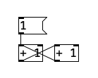
Here, the left-hand [+ 1] can't finish processing until the right-hand one has
been sent the result "2", which can't finish processing until the left-hand one
has been sent "3", and so on. This generates a "stack overflow" error (meaning there's
an infinite loop) in the Pd window that you can Ctrl+click
on (as described earlier) to select the causing object. Note that you can also use the
"Find Last Error" entry in the Find menu for this.
However, it is legal to make a loop if there is a [delay] object somewhere in it. When [delay] receives a message, it schedules a message for the future (even if the time delay is 0) and is then "finished"; Pd's internal scheduler will wake the [delay] back up later.
2.4.3. Hot and cold inlets and right to left outlet order
With few exceptions (notably [timer]), objects treat their leftmost inlet as
hot in the sense that messages to left inlets can result in output messages.
So the following is a legal (and reasonable) loop construct:
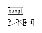
Here, the [f] object is an abbreviation for [float]. Note that the [+ 1] output is connected to the right-hand inlet of [f]. This cold inlet merely stores the value for the next time the [f] is sent the "bang" message.
It is frequently desirable to send messages to two or more inlets of an object to specify its action. For instance, you can use [+] to add two numbers; but to do it correctly you must make sure the right hand inlet gets its value first. Otherwise, when the left hand side value comes in, [+] will carry out the addition (since the left hand inlet is the "hot" one) and will add this value to whatever was previously sitting in the right hand inlet.
Problems can arise when a single outlet is connected (either directly or
through arbitrarily long chains of message passing) to different inlets of a
single object. In this case it is indeterminate which order the two inlets will
receive their messages. Suppose for example you wish to use [+]
to double a number. The following is incorrect:
Here, the left inlet was connected before connecting the right hand one (although this is not evident in the appearance of the patch). The [+] thus adds the new input (at left) to the previous input (at right).
The [trigger] object, abbreviated [t], can be used to split out connections from a single outlet in a determinate order. By convention, all objects in Pd, when sending messages out more than one outlet, do so from right to left. If you connect these to inlets of a second object without crossing wires, the second object will get its leftmost inlet last, which is usually what you want. Here is how to use [trigger] to disambiguate the previous example:
"Cold" (non-leftmost) inlets are almost universally used to store single values (either numbers or symbols). With the exception of [line], [line~] and [vline~], these values are "sticky", i.e., once you set the value it is good until the next time you set it. (The "line family" exception is for sanity's sake.)
One more question sometimes comes up concerning execution order when two messages are sent to a single "cold" inlet. In this situation, since the messages are merged, the last value to be received is the value that is used for the next computation.
2.4.4. Message boxes
Message boxes are text boxes in which you type a message. When the message box is activated, either by clicking on it or by sending something to its inlet, the message or messages are sent, either to the message box's outlet or elsewhere as specified.
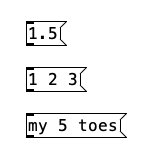
The first of the message boxes above contains the single number 1.5; this message has an implicit selector of "float". The second is a list with three numbers in it and has an implicit selector of "list". The third message has the selector "my" and the two arguments are the number 5 and the symbol "toes".
Multiple messages may be separated by commas as shown:
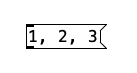
Here, the three messages are the numbers 1, 2, and 3, and they are sent in sequence (with no intervening time between them, as with the [trigger] object, and having depth-first consequences so that whatever chain of actions depending on "1" takes place before anything depending on "2" and so on).
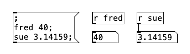
Semicolons may also separate messages. A message following a semicolon must
specify a symbol giving a destination (in other words, semicolons are like commas
except that they clear the "current destination" so that the next message
specifies a new one). The "current destination" is at first the message box's own
outlet. In the example below, the leading semicolon immediately redirects messages
from the outlet to an object named "fred" (which is a receive object here), and
likewise the next message is sent to "sue".
Certain other objects (Pd windows for example, and arrays) have Pd names as destination symbols so you can send them messages this way. Also, the special receiver "pd" is defined to which you may send messages to start and stop DSP and more.
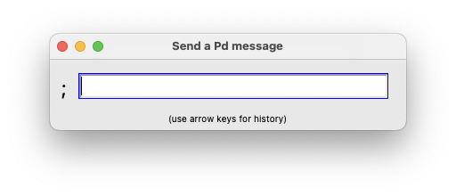
The File menu has a "Message..." entry that works as a message box with
a semicolon. This allows you to type in a message while in run mode. You need to
start the message with the receive symbol (and you can also send messages to "pd"
this way).
You can put variables in message boxes as shown below:
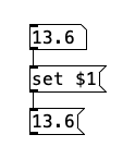
Here, "$1" etc., refer to the arguments of the arriving message (and aren't defined if you send a "bang" message or if you click on the message box to activate it). Dollar sign variables are either numbers or symbols depending on the incoming message; if they are symbols, you may even use them to specify variable message selectors or destinations.
2.4.5. Escaping characters
The "\" (backslash) character is used in Pd to escape special characters that are handled differently in Pd. Such characters are: "Space", "," (comma), ";" (semicolon) and "$" (dollar sign). Also, the backslash character itself can be escaped.
This way, the "Hi\, how are you?" message in a message box does not interpret the comma as it normally would, splitting the message in two. Instead, you have a literal comma and a "Hi" symbol. The help file of message boxes has examples on escaping characters, as well as information of previously discussed topics.
See also the "2.control.examples" from the documentation folder with more examples about messages and more.
2.5. Audio signals
Using Pd, you can build audio patches which can synthesize musical sounds, analyze incoming sounds, process incoming sounds to produce transformed audio outputs, or integrate audio processing with other media. This section describes how Pd treats audio signals.
2.5.1. Sample rate and format
Pd's audio signals are internally kept as 32-bit floating point numbers, so you have all the dynamic range you could want. However, depending on your hardware, audio I/O is usually limited to 16 or 24 bits. Inputs all appear between the values of -1 and 1; and output values will be clipped to that range. Pd assumes a sample rate of 44100 unless you override this (in Pd's command line or in the "audio setup" dialog).
Pd can read or write samples to files either in 16-bit or 24-bit fixed point or in 32-bit floating point, in 'wave', 'aiff', 'caf', and 'next' formats via the [soundfiler], [readsf~], and [writesf~] objects.
2.5.2. Tilde objects and audio connections
Audio computations in Pd are carried out by "tilde objects" such as [osc~], whose names conventionally end with a tilde character (which resembles a sinusoid, symbolizing their function in handling audio signals). Tilde objects can intercommunicate via audio connections. When audio computation is turned on or when you change the audio network while audio is on, Pd sorts all the tilde objects into a linear order for running; this linear list is then by default run down in blocks of 64 samples each at 44100 Hz. this means the audio network runs every 1.45 milliseconds.
Inlets or outlets are configured in Pd either for messages or audio. You can't connect an audio outlet to a non-audio inlet. An object's leftmost inlet may accept audio and message input; any other inlet is either one or the other, but secondary audio inlets take floats at control rate and promote them automatically to signals. Nonetheless, in some cases, the inlet may take a float or a signal and run different algorithms in each case. One example is [lop~], which runs a more efficient routine if no signals are connected to the right inlet. The [+~], [-~], [*~], [/~]. [max~], [min~], [log~] and [pow~] objects can be configured to take control or signal inputs in their 2nd inlet depending on the creation argument.
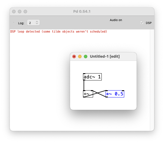
The audio network, that is, the tilde objects and their interconnections,
must be non-cyclic. If there are loops at "sort time", you will see an error
message on the main Pd window, saying "DSP loop detected (some tilde
objects weren't scheduled)".
You can build algorithms with feedback using nonlocal signal connections as explained in the 2.5.5. subsection.
Your subpatches can have audio inlets and outlets via the [inlet~] and [outlet~] objects (see 2.8. Subpatches).
2.5.3. Converting audio to and from messages
If you want to use a control value as a signal, you can use the [sig~] object to convert it. This is usually rare since objects mostly promote floats to signals as mentioned. At least this is true for all native objects in Pd, but there are externals that can behave differently. The [sig~] object is also useful for loading a default signal value with its creation argument. You can also use [line~] and [vline~] to "convert" from control to signal with a smoothing ramp, which can be quite useful.
The other direction, signal to control, requires that you specify at what moments you want the signal sampled. This is handled by the [snapshot~] object, but you can also sample a signal with [tabwrite~] and then access it via [tabread] or [tabread4] (note the missing tildes!) There are also analysis objects, the simplest of which is [env~], the envelope follower, that outputs control rate floats.
2.5.4. Switching and blocking
You can use the [switch~] or [block~] objects to turn portions of your audio computation on and off and to control the block size of computation. There may be only one [switch~] or [block~] object per window; it acts on the entire window and all of its subwindows (which may still have their own nested [switch~]/[block~] objects though). Both [switch~] and [block~] take a block size and optional overlap and up-/downsampling factors as arguments; so for instance, [block~ 1024 4] specifies 1024 sample blocks, overlapped by a factor of 4 relative to the parent window. The [switch~] version carries a small computational overhead in addition to whatever overhead is associated with changing the block size.
Larger block sizes than 64 should result in a small increase of runtime efficiency. Also, the [fft~] and related objects operate on blocks so that setting the block size also sets the number of FFT channels. You may wish to use block sizes smaller than 64 to gain finer resolutions of message/audio interaction, or to reduce "block delay" in feedback algorithms. At the extreme, setting the block size to 1 allows you to write your own recursive filters or other DSP algorithms that require a 1-sample-feedback.
You can use [switch~] to budget your DSP computations. For instance you might want to be able to switch between two synthesis algorithms. To do this, put each algorithm in its own subpatch (which can have sub-subpatches in turn, for a voice bank for instance), and switch each one off as you switch the other one on. Beware of clicks; if you have a [line~] controlling output level, give it time to ramp to zero before you switch it off or it will be stuck at a non-zero value for the next time it comes back on.
When a subpatch is switched off, its audio outputs generate zeros, which costs a fairly small overhead. A cheaper way to get outputs is to use [throw~] inside the switched module and [catch~] outside it.
2.5.5. Nonlocal signal connections
You may wish to pass signals non-locally, either to get from one window to another, or to feed a signal back to your algorithm's input. This can be done using [throw~]/[catch~], [send~]/[receive~], or [delwrite~]/[delread~] or [delread4~] pairs. Both [throw~] and [catch~] implement a summing bus; [throw~] adds into the bus and [catch~] reads out the accumulated signal and zeros the bus for the next time around. There can be many [throw~] objects associated with a single [catch~], but a [throw~] can't talk to more than one [catch~]. You can reset the destination of a [throw~] if you want to.
On the other hand, [send~] just saves a signal which may then be received by a [receive~] object any number of times; but a [receive~] can only pick up one [send~] at a time (you can switch between [send~] objects if you want though).
Don't try to [throw~] and [catch~] or [send~] and [receive~] between windows with different block sizes. The only well tested re-blocking mechanisms are [inlet~] and [outlet~].
When you send a signal to a point that is earlier in the sorted list of tilde objects, the signal doesn't get there until the next cycle of DSP computation (one block later), so your signal will be delayed by one block (1.45 msec by default). The [delwrite~] and [delread~]/[delread4~] have this same restriction, but here, the 1.45 msec are minimum attainable delay.
2.5.6. Multichannel signals
As of Pd version 0.54-0, signals may be multichannel. Every signal has a length equal to the window's block size (64 by default), and also has a channel count which is 1 by default. The [snake~] object can combine any number of single-channel signals into a multichannel one, or alternatively can split a multichannel signal into its component single-channel ones. Non-local connections ([send~], [receive~], [throw~], [catch~], [inlet~] and [outlet~]) can be used to pass multichannel signals from window to window, and [dac~] and [adc~] can input and output several inputs or outputs into, or out of one multichannel signal.
The [receive~], [catch~], and [adc~] objects take arguments to specify the desired number of channels.
Stateless objects, which have no memory from one DSP tick to the next, have all been adapted to handle multichannel inputs and outputs. The arithmetic and math objects ([+~], [-~], [*~], [/~], [wrap~], [sqrt~] and so on) use their inputs to determine their channel counts. Binary operations like [+~] can combine single- and multichannel inputs.
Other objects, such as filters or oscillators, have not been adapted for multichannel signals, because there might be many ways to design multichannel versions of them. Instead, you can use the [clone] object to perform general operations on multichannel signals. Signal inputs and outputs of cloned patches can be used to distribute multichannel signals among the individual cloned patches.
2.6. Scheduling
Pd uses 64-bit floating point numbers to represent time, providing sample accuracy and essentially never overflowing. Time appears to the user in milliseconds.
2.6.1. Audio and messages
Audio and message processing are interleaved in Pd. Audio processing
is scheduled every block (64 samples by default) at Pd's sample rate, which
is 44100 Hz by default and results in a period of approximately 1.45
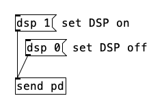
milliseconds. You may turn DSP computation on and off in a patch by sending
the messages "dsp 1" and "dsp 0" to "pd".
In the intervals between, delays might time out or external conditions might arise (incoming MIDI, mouse clicks or whatnot). These may cause a cascade of depth-first message passing; each such message cascade is completely run out before the next message or DSP tick is computed. Messages are never passed to objects during a DSP tick; the ticks are atomic and parameter changes sent to different objects in any given message cascade take effect simultaneously.
In the middle of a message cascade, you may schedule another one at a delay of zero. This delayed cascade happens after the present cascade has finished, but at the same logical time.
2.6.2. Computation load
The Pd scheduler maintains a (user-specified) lead on its computations; that is, it tries to keep ahead of real time by a small amount in order to be able to absorb unpredictable, momentary increases in computation time. This is specified using the "-audiobuf" and "-blocksize" command line flags (see 3.4.1. Startup flags).
If Pd gets late with respect to real time, gaps (either occasional or frequent) will appear in both the input and output audio streams. On the other hand, disk streaming objects will work correctly, so that you may use Pd as a batch program with soundfile input and/or output. The "-nogui" and "-send" startup flags are provided to aid in doing this.
Pd's "realtime" computations compete for CPU time with its own GUI, which runs as a separate process. A flow control mechanism will be provided someday to prevent this from causing trouble, but it is in any case wise to avoid having too much drawing going on while Pd is trying to make sound. If a sub-window is closed, Pd suspends sending the GUI update messages for it; but not so for minimized windows as of version 0.32 - you should really close them when you aren't using them.
2.6.3. Determinism
All message cascades that are scheduled (via [delay] and its relatives) to happen before a given audio tick will happen as scheduled, regardless of whether Pd as a whole is running on time; in other words, calculation is never reordered for any real-time considerations. This is done in order to make Pd's operation deterministic.
If a message cascade is started by an external event, a time tag is given to it. These time tags are guaranteed to be consistent with the times at which timeouts are scheduled and DSP ticks are computed; i.e., time never decreases. (However, either Pd or a hardware driver may lie about the physical time an input arrives; this depends on the operating system.) "Timer" objects which measure time intervals, measure them in terms of the logical time stamps of the message cascades, so that timing a [delay] object always gives exactly the theoretical value. (There is, however, a [realtime] object that measures real time, with nondeterministic results.)
If two message cascades are scheduled for the same logical time, they are carried out in the order they were scheduled.
2.7. Semantics
This section describes how objects in Pd are created, how they store data and how object and other boxes pass messages among themselves.
2.7.1. Creation of objects
The text in a box has a different function depending on whether it is a message, atom (number/symbol), or object box. In message boxes, the text specifies the message or messages it will send as output. In atom boxes, the text changes at run time to show the state of the box, which is either a number or a symbol.
In an object box, as in a message box, the text specifies a message; but here, the message is to be passed to Pd itself, once, and the message's effect is to create the object in question. When you open a file, all the objects created are created using their text as "creation messages". If you type a new message into an object box (or change it), the old object is destroyed and the message is used to create the new one.
The selector of the message (the first word in the message) is a selector which Pd interprets to determine the type of object to create. Any message arguments (called "creation arguments") are used to parametrize the object being created. Thus, in [makenote 64 250] the selector "makenote" determines the class of object to create and the creation arguments "64" and "250" become the initial velocity and duration.
2.7.2. Persistence of data
Among the design principles of Pd is that patches should be printable, in the sense that the appearance of a patch should fully determine its functionality. For this reason, if messages received by an object change its action, since the changes aren't reflected in the object's appearance, they are not saved as part of the file which specifies the patch and will be forgotten when the patch is reloaded. In the same way, if you delete and then recreate an object the original object's state is not retained but is instead reinitialized (possibly as specified by creation arguments).
An exception is made for subpatches whose "state" is the configuration of the subpatch; as a special case, this configuration is restored when the patch is read from a file. Also, if you rename the subpatch, for instance typing "pd jane" instead of "pd spot", the contents of the patch are preserved and only the text in the object box and the window title of the subpatch are changed.
It is probably bad style to specify creation arguments ala [makenote 64 250] if you are going to override them later; this is confusing to anyone who tries to understand the patch.
2.7.3. Message passing
Messages in Pd consist of a selector (a symbol) and zero or more arguments (which may be symbols or numbers). To pass a message to an object, Pd first checks the selector against the class of the object. Message boxes all are of one class and they all take the same incoming messages and dispense them according to their state, that is, the text typed into the box. The same holds for atom boxes (number or symbol) except that their state may change (it consists of the number or symbol showing).
Object boxes may have many different classes. The class is usually determined by the selector of the creation message, i.e., the first atom of the creation message which is usually a symbol.
Each class comes with a fixed collection of messages it may be sent. For example, the [float] or [f] object takes "bang" and "float". These messages are sent to [float] objects (objects whose class is float) via the leftmost, hot inlet (the right inlet is a separate, auxiliary object). Objects of class "float" respond to the message "bang" by outputting their current value, that is, by sending a "float" message to their outlet. They respond to "float" messages by setting their value and then outputting it.
Each other class (like [float]) in Pd has its own protocol for responding to messages it is sent, and may take "float" and "bang" messages, or others in addition or instead of them.
2.7.4. Inlets and lists
The leftmost connection point at the top of most objects represents the object itself. Any other dark rectangle is a separate object called an "inlet", although there are 4 different inlet classes in Pd. The class of the inlet determines the type of message it will accept: symbol, float or other; and the inlet passes the message either to the object itself or to a proxy, usually one created by the object for the occasion.
Unless they are specified otherwise by defining a "list" method, objects respond to the "list" message by distributing the arguments of the message to their inlets, except for the first argument, which is passed to the main object as a "float" or "symbol" message.
2.7.5. Dollar signs
In message or object boxes, message arguments starting with a dollar sign and a number (like "$1" or "$3-bazoo") are variables which are substituted with values supplied as part of the environment the message is passed in. In the case of message boxes, the environment consists of the arguments of the "list" message (possibly extrapolated from "bang", "float", or other) that the message box is responding to. Thus, if a message box gets "23 skidoo" and if it contains the text, "$2 until $1", out comes the message, "skidoo until 23".
Object boxes contain text which forms a message to be sent to Pd to create and initialize the object. Here, $1, etc., are taken from the context in which the patch was loaded. When the patch is a new document or opened from a file the "$" variables are undefined. But if the patch is an abstraction (see the next section) they are taken from the abstractions' creation arguments.
Constructions such as "$1-x" are expanded by string concatenation. This is the mechanism for making local variables. In particular, $0 is a counter, where every patch gets its own value. In an abstraction this guarantees a unique ID number to that abstraction, so sends and receives with names like "$0-bear" can be used as local send/receive pairs. This is also useful for things like array names, value names and text names (as defined in the text object).
Occasionally, you may want to have double or triple substitutions; this can be done one stage at a time by nesting abstractions (with each subpatch adding its own $-variable to a symbol and passing that on as argument to a further abstraction).
For example, if you want to get dog-food, dog-ears, and cat-food, for example, have an abstraction "a1" that invokes an abstraction "a2" twice, as "a2 $1-food" and "a2 $1-ears", and then in a third patch call a1 twice, as "a1 cat" and "a1 dog". Inside the four "a2" copies, $1 will evaluate to "dog-food", "cat-food", "dog-ears", and "cat-ears".
2.8. Subpatches
Pd offers two mechanisms for making subpatches, called "one-off subpatches"
and "abstractions". In either case the subpatch appears as an object box
in a patch. If you type [pd] or
[pd my-name] into an object box, this creates
a one-off subpatch. For instance, in this fragment:
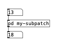
The box in the middle, if clicked on, opens the sub-patch shown here:
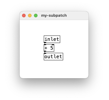
The contents of the subpatch are saved as part of the parent patch, in one file. If you make several copies of a subpatch you may change them individually.
The objects [inlet], [inlet~], [outlet] and [outlet~], when put in a subpatch, create inlets and outlets for the object box containing the subpatch. This works equally for one-off subpatches and abstractions and only accept control data messages. The [inlet~] and [outlet~] versions create inlets and outlets for audio signals. Note you can also mix control messages in an [inlet~] via its right outlet, but a signal outlet only takes signals. Inlets and outlets appear on the invoking box in the same left-to-right order as they appear in the subpatch.
2.8.1. Abstractions
To make an abstraction, save a patch with a name such as "abstraction1.pd"
and then invoke it in an object box as [abstraction1]:
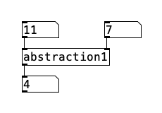
Here, we're invoking a separate file named "abstraction1.pd", which holds the
patch shown here:
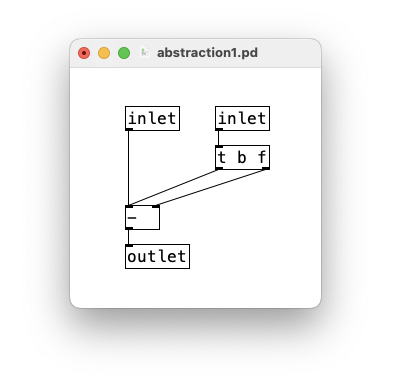
You may create many instances of [abstraction1] or invoke it from different patches. Changing and saving the contents of [abstraction1] will affect all invocations of it as they are created. An analogy from the "c" programming language is that one-off subpatches are like bracketed blocks of code and abstractions are like subroutines.
Abstractions are instantiated by typing the name of a patch (minus the ".pd" extension) into an object box. You may also type arguments; for instance if you have a file "my-abstraction.pd" you may have [my-abstraction 5] to set the variable "$1" to 5. This is defined only for object boxes (not for messages) in the abstraction. For message boxes, "$1", etc, have a different meaning as described above, so note that dollar signs are expanded at a different time in an object box than in a message box. In an object box, the "$" argument is expanded at creation time, and in a message box, at message time. If you want to send a message with a "$1" in the sense of a creation argument of an abstraction, you must generate it with an object box such as [float $1], [symbol $1], or perhaps [pack $1 $2], which may then be sent to a message box.
The [pdcontrol] object has an alternative strategy for retrieving arguments in an abstraction with the 'args' message, which makes the object output a list with all argument values. This has the advantage of being able to get a variable number of arguments, as well as varying their atom type.
A [clone] object is provided to automatically create and manage multiple copies of an abstraction. You can use it to make voice banks for polyphonic synthesis, for example.
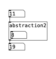
2.8.2. Graph-on-parent subpatches
If you open the "properties" dialog for a subpatch or an abstraction, you can
check the "graph on parent" box to have the controls of the subpatch/abstraction
appear on the parent. For instance, here is an invocation of [abstraction2]:
Where the patch "abstraction2.pd" contains:
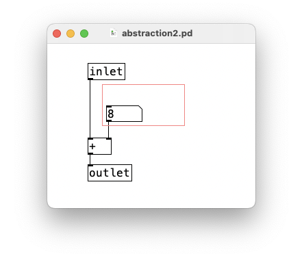
Here, the number box in the abstraction shows up on the box that invoked the abstraction. The "Graph-On-Parent" flag is set in the abstraction (and is saved as part of the abstraction); to set it, open the "Properties" dialog for the "abstraction2" canvas by right-clicking on any white space in the patch.
To open the subpatch, right click on the object and select "Open". It doesn't work just to click on the object in run mode since clicks are sent to visible controls and/or arrays.
When the sub-patch is closed, all controls in it appear on the object instead; so the number box in the sub-patch in the example above is the same one as you see in the box. Only controls are made visible in this way.
2.9. Arrays
Linear arrays of numbers recur throughout the computer musician's bag of tricks, beginning with the wavetable oscillator. The wavetable oscillator later was reinvented as the looping sampler. Also, table lookup is used for nonlinear distortion of audio signals. In the domain of control, arrays of numbers can specify control mappings, probability densities, voicing data, and much more.
Arrays in Pd should be allocated (and possible read in from a file) before beginning to make sound, since memory allocation and disk operations may take long enough to cause audio buffer overruns or underruns. Pd provides two ways to define new arrays, as "graphs" and "tables". In either case, the array has a predefined name and size (i.e., number of points). Elements of the array are stored as floating-point numbers, 4 bytes apiece.
If you use an array to store a one-second sound at 44.1 kHz, you will need 176 kilobytes, for a one-minute sound 10.6 megabytes. To store a sound with two or more channels, use a separate array for each channel.
Arrays are also useful as transfer functions, for example for nonlinear distortion of an audio signal, or to map a control onto a synthesis parameter. In situations like this, one typically uses much shorter arrays of no more than a few hundred elements. They are also useful for storing measured spectra derived from the fft~ objects, and probably for many other uses.
Arrays usually appear within subpatches created to house them, whether
in "graph on parent" form (so that you see them within a rectangle drawn on
the containing patch), or as a regular subpatch (which you see as a text box).
In the "graph on parent" form, an array appears as shown:
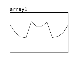
Arrays are indexed from 0 to N-1 where N is the number of points in the array.
You can use objects to read and write arrays and manipulate them in many ways.
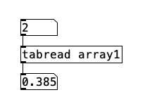
Here, we see that the third point of the array (index 2) has the value '0.385'.
To write into the array, you can use the [tabwrite] object:
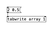
In this example, sending the message sets the third element to 0.5. (You may also send the two numbers to the two inlets separately.)
The two previous examples showed control operations to read and write from
and to arrays. These may also be done using audio signals. For example,
the patch below creates a 440 Hz tone with "array1" as a waveform:
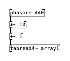
Here, [phasor~] outputs a ramp whose output range is from 0 to 1, repeating 440 times per second. The multiplier and adder adjust the range from 1 to 11 and then the values are used as indices for [tabread4~], which is a 4-point interpolating table lookup module. (Much more detail is available in the "3.audio.examples" series in the documentation folder.)
To create a new array, select "array" from the Put menu. A dialog will appear to set initial properties of the array. By default, a new graph is created to hold the array, but it may also be housed in the most recently created graph instead. Other properties may be specified there and/or changed later using the "Properties" dialog.
If you select "Properties" on an array in a graph, you get two dialogs, one
for the array and one for the graph. The array dialog looks like this:
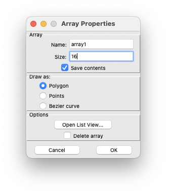
You may use this to change the name and size, in addition to another property, "Save contents". If "Save contents" is selected, the array's values are stored in the containing patch; otherwise they're initialized to zero each time the patch is reloaded. If you intend to use arrays to store sounds, you will probably not wish to store them in the patch but as separate soundfiles. This will be more efficient and you may also then use a sound editor to modify them outside Pd.
If you check "Delete array" and then "OK", the array will be deleted. This is an odd interface for deleting an object, and is only provided because Pd lacks a mechanism for selecting arrays (so that "cut" could serve this purpose).
The graph dialog (which also pops up) is shown here:
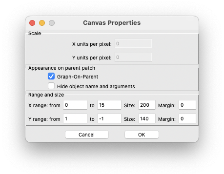
The X bounds initially range from 0 to the number of points in the table minus one (this is a good choice for arrays, although graphs holding other kinds of objects might require other X bounds). The Y bounds should be chosen to reflect the natural range of the table, so that stored sounds would naturally range from -1 to 1, but a sequence of frequency values might range from 0 to 20000. Finally, you choose the width and height of the graph in pixels.
Many other operations are defined for arrays; see the related patches in the tutorial (starting at 2.control/15.array.pd) for more possibilities.
2.10. Data structures
(Note: this section is an adapted and updated version of an article submitted to ICMC 2002.)
The original idea in developing Pd was to make a real-time computer music performance environment like Max, but somehow to include also a facility for making computer music scores with user-specifiable graphical representations. This idea has important precedents in Eric Lindemann's Animal and Bill Buxton's SSSP. An even earlier class of precedents lies in the rich variety of paper scores for electronic music before it became practical to offer a computer-based score editor. In this context, scores by Stockhausen ( Kontakte and Studie II) and Yuasa (Toward the Midnight Sun) come most prominently to mind, but also Xenakis's Mycenae-alpha, which, although it was realized using a computer, was scored on paper and only afterwards laboriously transcribed into the computer.
Pd is designed to to offer an extremely unstructured environment for describing data structures and their graphical appearance. The underlying idea is to allow the user to display any kind of data, associating it in any way with the display. To accomplish this Pd introduces a graphical data structure, somewhat like a data structure out of the C programming language, but with a facility for attaching shapes and colors to the data, so that the user can visualize and/or edit it. The data itself can be edited from scratch or can be imported from files, generated algorithmically, or derived from analyses of incoming sounds or other data streams.
There's a tutorial section dedicated to Data Structures (4.data.structures)
with many examples. Here is one simple example from this series (09.sequencer.pd)
with a very short musical sketch realized using Pd:
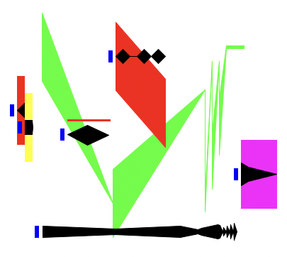
The example, which only lasts a few seconds, is a polyphonic collection of time-varying noise bands. The graphical "score" consists of six objects, each marked with a small blue rectangle at left and with data shapes: a black shape to show dynamic and a colored shape to show changing frequency and bandwidth. The horizontal axis represents time and the vertical axis, frequency (although, as explained later, this behavior isn't built into Pd). The dynamic and frequency shapes aren't constrained to be connected or even to be proximate, but since they pertain to the same sound their horizontal positions line up. In this example the last (furthest-right) object is percussive (as seen by the black shape) and has a fixed frequency and bandwidth, whereas the large, articulated shape in the center has a complicated trajectory in both frequency and amplitude. The color of the frequency has no purpose, but could be used to determine a voice number to route it.
Each object is thus composed of a combination of scalar values (color;
aggregate position in X and Y coordinates) and array values (time and envelope
pairs for the black traces and time, frequency and bandwidth triples for the
colored ones). This is all specified by the user using Pd's "template"
mechanism. Here is the template associated with the graphical objects shown
above.
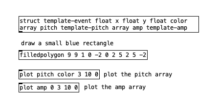
Templates consist of a data structure definition (the [struct] object) and zero or more drawing instructions (such as [filledpolygon] and [plot]). The [struct] object gives the template the name "template-event". The data structure is defined to contain three floating point numbers named "x", "y", and "color", and two arrays, one named "pitch" whose elements belong to another template named "template-pitch", and similarly for the array "amp" (both data structures contain three floating point numbers named "x", "y", and "w", for x/y position and width.)
In general, data structures are built from four data types: scalar floats and symbols, text and arrays (whose elements share another, specified template). The contents of a Pd window themselves form a list. Arrays are actually implemented as a top-level data structure array, whose elements are scalars containing a single floating-point number.
Data structures in Pd may nest arbitrarily deeply using the array and text types. For example, a collection of sinusoidal tracks from an analysis engine could be implemented as an array of arrays of (pitch, amplitude) pairs.
After the [struct] object in the template shown above, the remaining three objects are drawing instructions, first for a rectangle (with the [filledpolygon] object), and then for two arrays (with the [plot] objects). The various graphical attributes that are specified for drawing instructions may be numerical constants or data structure field names; in the latter case the value varies depending on the data. For instance, the second creation argument to [plot] is the color. The first one plots "pitch" using the color "color". In this way the color is attached to the "color" slot in the data structure, so that color will vary according to its "color" slot. The second [plot] plots the "amp" field and the color is given as 0, which is black.
2.10.1. Traversal
Pd objects are provided to traverse lists and arrays, and to address elements of data structures for getting and setting. Pd has no built-in sequencer, nor even any notion that "x" values should be used as a time axis. (However, a "sort" function is provided, which reorders a list from left to right, on the assumption that users might often want to use Pd data collections as x-ordered sequences.) Recording sequences of events into lists, and/or playing the lists back as sequences, are functionalities that the user is expected to supply on top of Pd's offerings, which, it is hoped, would allow those functionalities within a much larger range of possibilities, to include random re-orderings of events, score following, self-modifying scores, reactive improvisation, and perhaps much more.
Here is a screenshot of the subpatch that implements the graphical sequence
score shown above. It takes a 'start' or 'stop' message and the sequencing is
done in the [pd sequence] subpatch. It also uses the [clone] object to
instantiate different copies of the [voice] abstraction, which is
responsible for synthesizing each voice from the score.
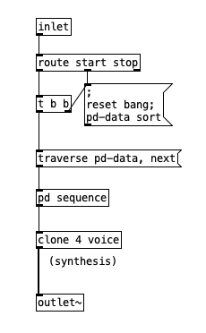
Traversal of data is made possible by adding a new type of atom, "pointer",
to the two previously defined types that make up messages (numbers and symbols).
Unlike numbers and symbols, pointers have no printed form and thus can't be
uttered in message boxes. Traversal objects such as [pointer] and
[get](among several others) can generate or use pointers. The pointer
data type is also integrated into pipe-fitting objects such as [pack],
[unpack], and [route]. The [trigger] object also deals
with pointers.
![[pd sequence] subpatch](resources/2.10.4.png)
In the [pd sequence] subpatch shown above, a first [pointer] object is used to traverse through the data. It first takes a "traverse" message (sent from the parent) to set it to the head of the list (named "pd-data"), and "next" messages to move to (and output) the next datum in the list (i.e., the next in the list of six objects in the score).
A second [pointer] object is used here as a storage cell for pointers just as [float] is for numbers. The center of the sequencer is the [delay] object, which must be fed the time difference between each event (including the non-event of hitting "start") and the next.
The time difference needed to set the [delay] object is obtained using the [get template-event] object with the 'x' field. This is converted to incremental time with [-], corrected for tempo, and fed to the [delay] object. Pd provides the [get] and [set] objects for reading and writing values from data structures. The [get] object shown here obtains the "x" and "y" fields of the current object. The template name (template-event) is supplied to the [get] objects so that they can look up the offset of the necessary field(s) in advance, for greater run-time efficiency.
As we extract each of the six objects in the score, we must wait the delay for playing
that object. Once the delay time has expired, the object's pointer is recalled with the second
[pointer] object and packed with the pitch base value to cloned instances of the
[voice] abstraction (for that a 'next' message is prepended to the list, which is
needed by [clone]). Let's check the [voice] abstraction below.
![[voice] abstraction](resources/2.10.5.png)
The pointer and pitch value are unpacked. The pointer value is sent to [data-array]
abstractions, which extract the pitch and dynamic breakpoints from the arrays (specified as
the abstraction's argument,) so it contains two sub-sequencers itself. The nesting of
the overall structure of the sequencer patch mirrors the nesting of the original data
structures. Let's have a look at the [data-array] abstraction below.
![[data-array] abstraction](resources/2.10.6.png)
We have to inspect the object itself to know the delay before playing it. So, in the loop, we peel off the first remaining object to play and inspect the time difference between it and the previous one, using this value to set the [delay] object.
More general patches can easily be constructed which access heterogeneous lists of objects (having different templates). In this way, an arbitrarily rich personal "score language" can be developed and sequenced.
2.10.2. Accessing and changing data
In general, accessing or changing data is done via "pointers" to "scalars". Numbers and symbols within scalars are accessed using the [get] object and changed, in the same way, using [set]. Since lists and arrays are composed of scalars, every actual number or symbol in a data heap will be a number or symbol element of some scalar. To access them, it suffices to have objects to chase down elements of lists and arrays (given either a global name or a pointer to the containing scalar).
Lists are traversed in the way shown above; to get to a sublist of a scalar, the [get] object will provide a pointer, in the same way as it provides "float" or "symbol" elements of scalars. For arrays, an [element] object is provided which, given a scalar, a field name and a number, chases down the numbered, scalar, element of the named array field.
To alter "float" or "symbol" elements of scalars is straightforward using the [set] object, but arrays and lists can't be set by assignment; there is no suitable data type available within messages. Lists could possibly be "settable" by passing pointers to other lists, but permitting this would have required either automatically doing deep copies of data structures to carry out the assignments, or else implementing a garbage collecting memory management system, either of which would be difficult to realize within real-time computation time constraints. Instead, all the data hanging from a scalar is considered as belonging to that scalar, and is left in memory until the scalar is deleted; the data may be changed atom by atom, but primitives are not provided which would imply unpredictable execution times.
The [getsize] and [setsize] objects are provided to access or change the number of elements in the array. For lists, an [append] object appends a new scalar for a given template to a list, after the element pointed to. (To insert a scalar at the beginning of a list, the pointer can be set to the "head" of the list, a formal location before the first list item.) Deletion is less flexible; the only operation is to delete an entire list. (There's no reason not to provide finer-grain deletion mechanisms except that it's not clear how to protect against stale pointers efficiently, except by voiding the entire collection of pointers into a list.)
2.10.3. Editing
The graphical score shown above can be edited by dragging breakpoints, or by adding and deleting them, using mouse clicks. Also, entire objects or collections of them may be copied, pasted, and dragged around the screen. Alternatively, there is an editable (or computer generate-able or parse-able) text representation for the data, which may be seen or changed in a dialog window or read and written to external text files.
Since the graphical presentation of data objects is determined by drawing instructions, the drawing instructions are interpreted backward to alter data as a result of mouse operations. If a given graphical dimension is controlled by a variable, that variable is then controlled by dragging along that dimension; if the dimension is constant, it can't be altered by dragging.
Tricky situations can arise when the user changes the contents of templates. A change in drawing instructions can be accommodated by simply tracking down and redrawing all data objects using the template. However, changing the [struct] object itself make for less straightforward situations. The user might wish to reorder fields, delete them, add new ones, or rename them. When a [struct] object changes, Pd automatically conforms the data from the old structure to the new one. Fields with the same name as previously are maintained (reordering them as necessary) and if a field disappears but another of the same type appears, the new one(s) are taken to be renamings of the old one(s) in order of appearance. New fields which cannot be matched in this way with previously existing ones are assumed to be new and are initialized.
It can happen that two [struct] objects compete to define the same data structure, or that the user reads in data from a file which expects a different version of the structure, or alternatively, that the [struct] object for existing data objects disappears. For this reason, Pd maintains a private representation of the last active version of a [struct] until all similarly named "structs", as well as all data using that "struct", have disappeared. If the user introduces a new version of the "struct" and only later deletes the "current" one, the data is only conformed to the new version once the old one is deleted. In this way we avoid getting into situations where data is left hanging without its structure definition, or where data ends up belonging to two or more structures of the same name. The worst that can happen is that data may lose their drawing instructions, in which case Pd supplies a simple default shape.
2.10.4. Limitations
When examples get more complicated and/or dense than the one shown here, it becomes difficult to see and select specific features of a data collection; more work is needed to facilitate this. There should be some facility for turning drawing instructions on and off, or perhaps for switching between versions of a template, depending on the user's desired view. There should also be a callback facility in the template for when an object is edited with the mouse, so that the user can bind actions to mouse clicks.
More generally, the collection of traversal objects that Pd provides is adequate to support a variety of modes of data collection and use, such as analysis and sequencing. But the patches required to traverse the data collections are not always simple. It would be desirable to find a more straightforward mechanism than that provided by the [pointer], [get] and [set] objects.
The "data" facility, although part of the original plan for Pd, has only recently been implemented in its current form, and as (hopefully) the user base grows there will surely be occasions for many further extensions of the data handling primitives and the graphical presentation and editing functions.
2.11. Pd vs. MAX
You may be aware that Miller Puckette, the creator and author of Pd, was also the original creator and author of MAX, which was developed in the 1980s at IRCAM. Pd was designed later with first drafts from 1996 and it does resemble the MAX system. This section addresses the relationship between the two environments.
Some external objects and libraries for MAX are also provided for Pd (such as 'Flucoma', 'FFTease', 'soundhack' and more). This depends on the will and intent of the external developer though. In the early days, it was easier to design externals that could run in both systems, but the APIs diverged over the years.
2.11.1. Differences between Pd and MAX
Although Pd wasn't intended to be a MAX clone, there were many similarities in its origin and some effort had been undertaken to make the two interoperable. It was possible to import and export patches from and to MAX/MSP; you just needed to save as text to a file with extension '.pat' and then open in the other program to get at least some results. By sticking to common or commonizable features, you could develop patches for both platforms.
To this day, Pd can still open and save MAX patches with the '.pat' extension as well as MAX text files with the '.mxt' extension. However, these are legacy and unsupported MAX formats. Today, MAX uses a JSON-based file format with the '.maxpat extension introduced in MAX 5, released in 2008.
Since then, MAX and Pd have futher diverged, but Pd is still closely related to MAX/MSP. Nonetheless, there are differences in semantics between the two; a partial list follows.
In MAX, there are separate data types for integers and floating point numbers. You can use a '.' at the end of the number to specify it as a float, which may be needed as argument is some objects. Similarly MAX has a 'float' and an 'int' list selector that you can use to define whether a '1' is a float or an int in a message. Pd only has a float type and selector, so you don't need to worry about any of this - all numbers are floats and there is no distinction between '1' and '1.'. This gives MAX a higher integer resolution, but with the double precision version of Pd (Pd64), this is also not a significant issue anymore.
MAX has a 'list' selector, but it is always implicit. In Pd it is only implicit if the list starts with a float. If you have a list that starts with a symbol, you need the 'list' selector in Pd. MAX has no 'symbol' selector and Pd explicitly needs it to define a symbol data type.
In MAX, you can put a list inside quotes to specify a symbol, so "a b c" or "1 2 3" are actually a single symbol. Pd has no quote mechanism but you can escape spaces and form a symbol with it, so a\ b\ c and 1\ 2\ 3 actually form symbols. In MAX, you can also force a float to become a symbol with "1", in Pd this is trickier, since anything that looks like numbers are floats - but you can use [makefilename] to turn a number into a symbol.
In MAX, if an object's outlet is connected to several inlets, corresponding messages are always sent in right-to-left order of the inlets' positions. In Pd, the messages are sent in the order that the connections were made. Either way, when you care about the order, it's appropriate to use a [trigger] object to clearly define it.
In Pd, [inlet] / [outlet] and [inlet~] / [outlet~] are regular objects, whereas in MAX they're GUI objects and work for signal and control data.
MAX offers many GUI objects such as sliders, dials, VU meters, piano keyboards, even 'bpatchers'. Up until version 0.34, the only two GUI objects in Pd were number box and graphical arrays. Starting from version 0.34, Pd incorporates Thomas Musil's GUI objects: sliders, switches and so on (Thanks Thomas!). Beyond this essential collection of GUI objects, it's unlikely that you'll ever find any commonality between the two, unless you install externals that offer more GUI options in Pd.
Pd's correlate of MAX's [poly~] object is [clone]. In Pd, there is no [pfft~] object for managing spectral processing and you just use regular subpatches or abstractions that are adapted for it.
Pd has multichannel connections, but currently, no visual distinction is made. In MAX, you need to create a special version of the object, such as [mc.+~], which actually is a wrapper that loads [+~] for multichannel capabilities. In Pd, objects like [+~] simply also work for multichannel and [clone] can be used to customly wrap abstractions and give them multichannel capabilities if you are using objects without multichannel features.
In abstractions, the corresponding feature for '$1' in Max is the '#1' construct. In a MAX abstraction, '#1' etc. are replaced by the creation argument when you have a look at the patch. In Pd, the '$' variables in object boxes are always spelled literally as '$' variables. Patches in Pd are also ready to be edited, while an abstraction in MAX is locked and "Read Only" if you open it; but can be edited in place using the "Modify Read Only" command. If you then unlock the abstraction to edit it, you can see the '$1' variables.
In MAX, the same '#1' construct is used to expand abstraction or clone arguments in messages, while Pd can only use '$1' for objects' variables and you cannot load arguments in messages. In that case, you need to use '$1' inside an object and then send it to a message with a '$1' variable.
In MAX, the local patch ID '#0' is used for objects and messages, but only inside abstractions. In Pd, you can use '$0' only as an object argument, but it also gets expanded when not loaded in abstractions. Also, unlike Pd, MAX does not let you open multiple copies of the same patch document.
MAX has a [pv] object that is like [value] and can force locality of variables in subpatches. In Pd, you need to set different names to [value] in each subpatch.
In Pd, you can change the send destination of a [send] object, while in MAX, you can set the receive name in a [receive] object. The [float], [int] and [value] objects in Pd have a built-in 'send' message that communicates to receive addresses. GUIs in Pd have built-in 'send' and 'receive' names. The [expr] object in Pd can load variables defined by [value].
In Pd, if you select "save" while in a subpatch, the parent is saved. In MAX, you can only save from the parent and you can save the subpatch as a separate file (if you want to save a subpatch to a file in Pd, you have to copy and paste the contents to a new document).
In Pd, there's no [gate]; instead there's a [spigot] with the inlets in the opposite, more natural order.
Switching subsets of the DSP patch on and off is done in completely different ways in Pd and MAX, and block sizes are handled differently as well.
The 'bpatcher' feature in MAX has a correlate in Pd (Graph-on-parent subpatches); however, Pd's version is quite different from the one in MAX.
Pd's correlate of Max's [itable] object are arrays implemented as a high level data structure construct.
In Pd, there's no [preset], [pattrstorage] or related object. This is intentional, as Miller considers this to be basically a bad idea, so you have to use explicit sends and receives to restore values to number boxes. Then just make a "message" box to re-send the values you want. You can also save data as text from arrays and [text] objects. Also, a [savestate] is provided to save the state of different instances of an abstraction within the parent patch.
In MAX, using [tabosc4~] with an array, you'd use [cycle~] with [buffer~]. The only gotcha is that you can't draw in [buffer~] with the mouse like you can with arrays in Pd - but at least it's possible to make a patch that copies a 'table' into a [buffer~] object.
MAX can deal with multi-core processing, while Pd relies on an object called [pd~] for that, which opens a new Pd subprocess.
2.11.2. Running Pd inside MAX with the [pd~] external
There is a MAX version of the [pd~] object. If you install this external for MAX, you can run Pd as a subprocess inside MAX. A download of the external is provided at https://msp.ucsd.edu/software.html.
This allows you to run not only Pd's core objects, but also any external you might have
installed for Pd. The picture below shows a [pd~] object in MAX 8.
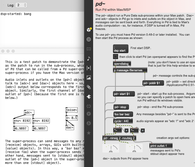
2.11.3. The Cyclone library
The Cyclone library for Pd includes a collection of objects cloned from MAX and includes control (MAX) and signal (MSP) objects. This can be useful for MAX users to feel more at home and adapt MAX patches in Pd. For more details, please check https://github.com/porres/pd-cyclone.
Cyclone is an old and legacy external library for Pd. It was created and developed by Krzysztof Czaja from 2002 to 2005. A recent update by Alexandre Porres, Derek Kwan and Matt Barber has included some new objects and paired up Cyclone to MAX version 7.3.5. Currently, Cyclone is under maintenance mode, so don't expect updates besides bug fixes. No new objects are planned.
Note that other external libraries may offer functionalities and alternatives to MAX objects though (while Cyclone's aim is to exactly imitate MAX objects - even with their flaws). For instance, the main current maintainer of Cyclone (Porres) develops the ELSE library, which has alternatives for almost all cyclone objects and many objects in ELSE are actually inspired by MAX/MSP objects that were not cloned in Cyclone. The 'ceammc' library also provides a complete and cohesive system with lots of GUIs and functions you can find in MAX.