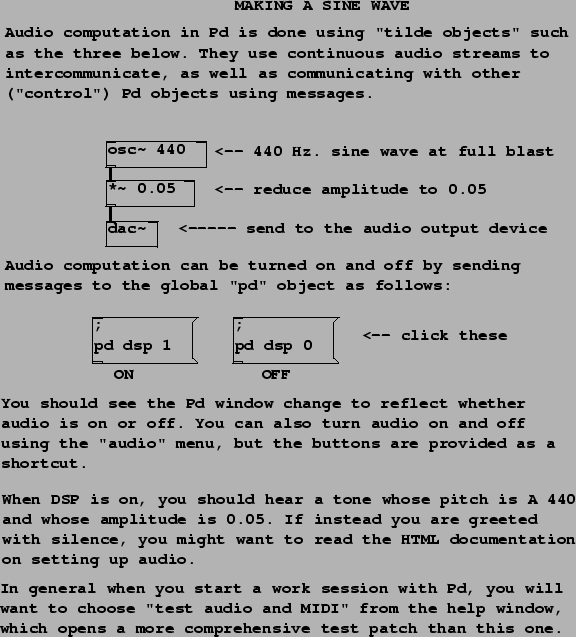
Patch A01.sinewave.pd, shown in figure 1.7, contains essentially the simplest possible noise-making patch, with only three object boxes. (There are also comments, and two message boxes to turn Pd's ``DSP" (audio) processing on and off.) The three object boxes are:
![]() : the sinusoidal oscillator. The left hand side input and
the output take digital audio signals. The input is taken to be a
(possibly time-varying) frequency in Hz. The output is a SINUSOID
at the specified frequency. If nothing is connected to the
frequency inlet, the creation argument (440 in this example) is
used as the frequency. The output has peak amplitude one. You may
set an initial phase by sending messages (not audio signals) to the
right inlet. The left (frequency) inlet may also be sent messages
to set the frequency, since any inlet that takes an audio signal
may be sent messages which are automatically converted to the
desired audio signal.
: the sinusoidal oscillator. The left hand side input and
the output take digital audio signals. The input is taken to be a
(possibly time-varying) frequency in Hz. The output is a SINUSOID
at the specified frequency. If nothing is connected to the
frequency inlet, the creation argument (440 in this example) is
used as the frequency. The output has peak amplitude one. You may
set an initial phase by sending messages (not audio signals) to the
right inlet. The left (frequency) inlet may also be sent messages
to set the frequency, since any inlet that takes an audio signal
may be sent messages which are automatically converted to the
desired audio signal.
![]() : the multiplier. This exists in two forms. If a creation
argument is specified (as in this example; it's 0.05), this box
multiplies a digital audio signal (in the left inlet) by the
number; messages to the right inlet can update the number as well.
If no argument is given, this box multiplies two incoming digital
audio signals together.
: the multiplier. This exists in two forms. If a creation
argument is specified (as in this example; it's 0.05), this box
multiplies a digital audio signal (in the left inlet) by the
number; messages to the right inlet can update the number as well.
If no argument is given, this box multiplies two incoming digital
audio signals together.
![]() : the audio output device. Depending on your hardware, this
might not actually be a Digital/Analog Converter--as the name
suggests--but in general, it allows you to send any audio signal to
your computer's audio output(s). If there are no creation
arguments, the default configuration is to output to channels one
and two of the audio hardware; you may specify alternative channel
numbers (one or many) using the creation arguments. Pd itself may
be configured to be using two or more output channels, or may not
have the audio output device open at all; consult the Pd
documentation for details.
: the audio output device. Depending on your hardware, this
might not actually be a Digital/Analog Converter--as the name
suggests--but in general, it allows you to send any audio signal to
your computer's audio output(s). If there are no creation
arguments, the default configuration is to output to channels one
and two of the audio hardware; you may specify alternative channel
numbers (one or many) using the creation arguments. Pd itself may
be configured to be using two or more output channels, or may not
have the audio output device open at all; consult the Pd
documentation for details.
The two message boxes in example 1 show a peculiarity in the way messages are parsed in message boxes. In the previous example, the message consisted only of the number 21. When clicked, that box sent the message ``21" to its outlet and hence to any objects connected to it. In the current example, the text of the message boxes starts with a semicolon. This is a terminator between messages (so the first message is empty), after which the next word is taken as the name of the recipient of the following message. Thus the message here is ``dsp 1" (or ``dsp 0") and the message is to be sent, not to any connected objects--there aren't any anyway-- but rather, to the object named ``pd". This particular object is provided invisibly by the Pd program and you can send it various messages to control Pd's global state, in this case turning audio processing on (``1") and off (``0").
Many more details about the control aspects of Pd, such as the above, are explained in a different series of example patches (the ``control examples") as part of the Pd release, but they will only be touched on here as necessary to demonstrate the audio signal processing aspects that are the subject of this book.