One application area requiring careful thought about the control stream/audio signal boundary is sampling. Until now our samplers have skirted these issues by looping perpetually. This allows for a rich variety of sound that can be accessed by making continuous changes in parameters such as loop size and envelope shape. However, many uses of sampling require the internal features of a sample to emerge at predictable, synchronizable moments in time. For example, percussion samples are usually played from the beginning, are not often looped, and are usually played in some kind of determined time relationship with the rest of the music.
In this situation, control streams are better adapted than audio
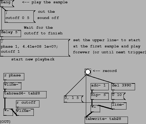
signals as triggers. Example patch C05.sampler.oneshot.pd (Figure
3.14) shows one possible way to
accomplish this. The four tilde objects at bottom left form the
signal processing network for playback. One
![]() object generates a phase
signal (actually just a table lookup index) to the
object generates a phase
signal (actually just a table lookup index) to the
![]() object; this replaces
the
object; this replaces
the
![]() of patch
B02.wavetable.FM.pd(page
of patch
B02.wavetable.FM.pd(page ![]() ) and its
derivatives.
) and its
derivatives.
The amplitude of the output of
![]() is controlled by a
second
is controlled by a
second
![]() object. This is in order
to prevent discontinuities in the output in case a new event is
started while the previous event is still playing. The ``cutoff"
object. This is in order
to prevent discontinuities in the output in case a new event is
started while the previous event is still playing. The ``cutoff"
![]() ramps the output down to
zero (whether or not it is playing) so that, once the output is
zero, the index of the wavetable may be changed
discontinuously.
ramps the output down to
zero (whether or not it is playing) so that, once the output is
zero, the index of the wavetable may be changed
discontinuously.
The sequence of events for starting a new ``note" is, first,
that the ``cutoff"
![]() is ramped to zero; then,
after a delay of 5 msec (at which point
is ramped to zero; then,
after a delay of 5 msec (at which point
![]() has reached zero) the
phase is reset. This is done with two messages: first, the phase is
set to 1 (with no time value so that it jumps to 1 with no
ramping.) This is the first readable point of the wavetable.
Second, in the same message box, the phase is sent to 441,000,000
over a time period of 10,000,000 msec. This corresponds to 44.1
units per millisecond and thus to a transposition of one. The upper
has reached zero) the
phase is reset. This is done with two messages: first, the phase is
set to 1 (with no time value so that it jumps to 1 with no
ramping.) This is the first readable point of the wavetable.
Second, in the same message box, the phase is sent to 441,000,000
over a time period of 10,000,000 msec. This corresponds to 44.1
units per millisecond and thus to a transposition of one. The upper
![]() (which generates the
phase) receives these messages via the
(which generates the
phase) receives these messages via the ![]()
![]() object above it.
object above it.
The example assumes that the wavetable is ramped smoothly to
zero at either end, and the bottom right portion of the patch shows
how to record a sample (in this case four seconds long) which is
ramped smoothly to zero at either end. Here a regular (and
computationally cheaper)
![]() object suffices. Although
the wavetable should be at least 4 seconds long for this to work,
you may record shorter wavetables simply by cutting the
object suffices. Although
the wavetable should be at least 4 seconds long for this to work,
you may record shorter wavetables simply by cutting the
![]() object off earlier. The
only caveat is that, if you are simultaneously reading and writing
from the same sample, you may have to avoid situations where read
and write operations attack the same portion of the wavetable at
once.
object off earlier. The
only caveat is that, if you are simultaneously reading and writing
from the same sample, you may have to avoid situations where read
and write operations attack the same portion of the wavetable at
once.
The
![]() objects surrounding the
objects surrounding the
![]() were chosen over
were chosen over
![]() because the latter's
rounding of breakpoints to the nearest block boundary (typically
1.45 msec) can make for audible aperiodicities in the sound if the
sample is repeated more than 10 or 20 times per second, and would
prevent you from getting a nice, periodic sound at higher rates of
repetition.
because the latter's
rounding of breakpoints to the nearest block boundary (typically
1.45 msec) can make for audible aperiodicities in the sound if the
sample is repeated more than 10 or 20 times per second, and would
prevent you from getting a nice, periodic sound at higher rates of
repetition.
We will return to
![]() -based sampling in the next
chapter, to add transposition, envelopes, and polyphony.
-based sampling in the next
chapter, to add transposition, envelopes, and polyphony.