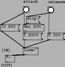
Patch D01.envelope.gen.pd (figure 4.12) shows how the line~ object may be used to generate an ADSR envelope to control a synthesis patch (only the ADSR envelope is shown). The ``attack" button, when pressed, sets off two chains of events. The first (leftmost in the figure) is to set the line~ object on its attack segment, with a target of 10 (the peak amplitude) over 200 msec (the attack time). Second, the attack button sets a delay 200 object, so that after the attack segment is done, the decay segment can start. The decay segment goes to a target of 1 (the sustain level) after another 2500 msec (the decay time).
The ``release" button sends the same line~ object beck to zero over 500 more milliseconds (the release time). Also, in case the delay 200 object happens to be set at the moment the ``release" button is pressed, a stop message is sent to it. This prevents the ADSR generator from launching its decay segment after launching its release segment.
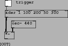
In patch D02.adsr.pd (figure 4.13) we encapsulate the ADSR generator in a Pd abstraction (named adsr) so that it can easily be replicated. The design of the adsr abstraction makes it possible to control the five ADSR parameters either by supplying creation arguments or by connecting control streams to its inlets.
In this example the five creation arguments (1, 100, 200, 50, and 300) specify the peak level, attack time, decay time, sustain level (as a percentage of peak level), and release time. There are six control inlets: the first to trigger the ADSR generator, and the others to update the values of the five parameters. The output of the abstraction is an audio signal.
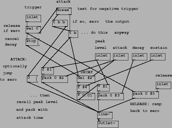
This abstraction is realized as shown in figure 4.14. (You can open this patch by clicking on the adsr object in the patch.) The only signal objects are line~ and outlet~The three pack objects correspond to the three message objects from the earlier figure 4.12. They take care of the attack, decay, and release segments.
The attack segment goes to a target specified as $1
(the first creation argument of the abstraction) over
$2 milliseconds; these values may be overwritten by
sending numbers to the ``peak level" and ``attack" inlets. The
release segment is similar except simpler since the target is
always zero. The hard part is the decay segment, which again must
be set off after a delay equal to the attack time (the del
$2 object). The sustain level is calculated from the peak
level and the sustain percentage (multiplying the two and dividing
by 100).
The trigger inlet, if sent a number other than zero, triggers an onset (the attack and decay segments), and if sent zero, triggers the release segment. Furthermore, the ADSR generator may be reset to zero by sending a negative trigger (which also generates an onset).