In most widely used audio synthesis and processing packages (Csound, Max/MSP, and Pd, for instance), the audio operations are specified as networks of unit generators which pass audio signals among themselves. The user of the software package specifies the network, sometimes called a patch, which essentially corresponds to the synthesis algorithm to be used, and then worries about how to control the various unit generators in time. In this section, we'll use abstract block diagrams to describe patches, but in the "examples" section later, we'll have to choose a real implementation environment and show some of the software-dependent details.
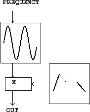
To show how to produce a sinusoid with time-varying amplitude we'll need to introduce two unit generators. First we need a pure, SINUSOID which is produced using an oscillator. Figure 1.2(a) shows the icon we use to show a sinusoidal oscillator. The input is a frequency (in cycles per second), and the output is a SINUSOID of peak amplitude one.
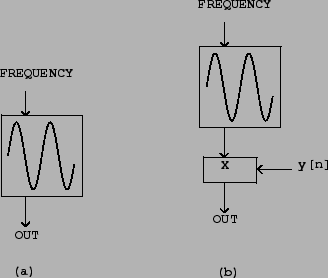 |
Figure 1.2(b) shows how to
multiply the output of a sinusoidal oscillator by an appropriate
amplitude scaler ![]() to control its amplitude. Since
the oscillator's peak amplitude is 1, the peak amplitude of the
product is about
to control its amplitude. Since
the oscillator's peak amplitude is 1, the peak amplitude of the
product is about ![]() , assuming
, assuming ![]() changes
slowly enough and doesn't become negative in value.
changes
slowly enough and doesn't become negative in value.
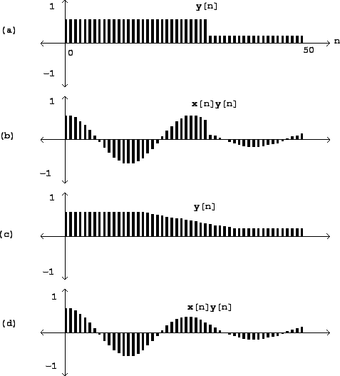 |
Figure 1.3 shows how the
SINUSOID of Figure 1.1 is
affected by amplitude change by two different controlling signals
![]() . In the first case the controlling signal
shown in (a) has a discontinuity, and so therefore does the
resulting amplitude-controlled sinusoid shown in (b). The second
case (c, d) shows a more gently-varying possibility for
. In the first case the controlling signal
shown in (a) has a discontinuity, and so therefore does the
resulting amplitude-controlled sinusoid shown in (b). The second
case (c, d) shows a more gently-varying possibility for ![]() and the result. Intuition suggests that the result shown
in (b) won't sound like an amplitude-varying sinusoid, but instead
by a sinusoid interrupted by a fairly loud ``pop" after which the
sinusoid reappears more quietly. In general, for reasons that can't
be explained in this chapter, amplitude control signals
and the result. Intuition suggests that the result shown
in (b) won't sound like an amplitude-varying sinusoid, but instead
by a sinusoid interrupted by a fairly loud ``pop" after which the
sinusoid reappears more quietly. In general, for reasons that can't
be explained in this chapter, amplitude control signals ![]() which ramp smoothly from one value to another are less
likely to give rise to parasitic results (such as the ``pop" here)
than are abruptly changing ones. Two general rules may be suggested
here. First, pure sinusoids are the class of signals most sensitive
to the parasitic effects of quick amplitude change; and second,
depending on the signal whose amplitude you are changing, the
amplitude control will need between 0 and 30 milliseconds of
``ramp" time--zero for the most forgiving signals (such as white
noise), and 30 for the least (such as a sinusoid). All this also
depends (in complicated ways) on listening levels and the acoustic
context.
which ramp smoothly from one value to another are less
likely to give rise to parasitic results (such as the ``pop" here)
than are abruptly changing ones. Two general rules may be suggested
here. First, pure sinusoids are the class of signals most sensitive
to the parasitic effects of quick amplitude change; and second,
depending on the signal whose amplitude you are changing, the
amplitude control will need between 0 and 30 milliseconds of
``ramp" time--zero for the most forgiving signals (such as white
noise), and 30 for the least (such as a sinusoid). All this also
depends (in complicated ways) on listening levels and the acoustic
context.
Suitable amplitude control functions ![]() may be
obtained using an envelope
generator. Figure 1.4 shows a
network in which an envelope generator is used to control the
amplitude of an oscillator. Envelope generators vary widely in
functionality from one design to another, but our purposes will be
adequately met by the simplest kind, which generates line segments,
of the kind shown in fig. 1.2(b).
If a line segment is specified to ramp between two output values
may be
obtained using an envelope
generator. Figure 1.4 shows a
network in which an envelope generator is used to control the
amplitude of an oscillator. Envelope generators vary widely in
functionality from one design to another, but our purposes will be
adequately met by the simplest kind, which generates line segments,
of the kind shown in fig. 1.2(b).
If a line segment is specified to ramp between two output values
![]() and
and ![]() over
over ![]() samples starting at sample number
samples starting at sample number ![]() , the output
is:
, the output
is:
In addition to changing amplitudes of sounds, amplitude control is often used, expecially in real-time applications, simply to turn sounds on and off: to turn one off, ramp the amplitude smoothly to zero. Most software synthesis packages also provide ways to actually stop modules from computing samples at all, but here we'll use amplitude control instead.
Envelope generators are described in more detail in section 4.1.