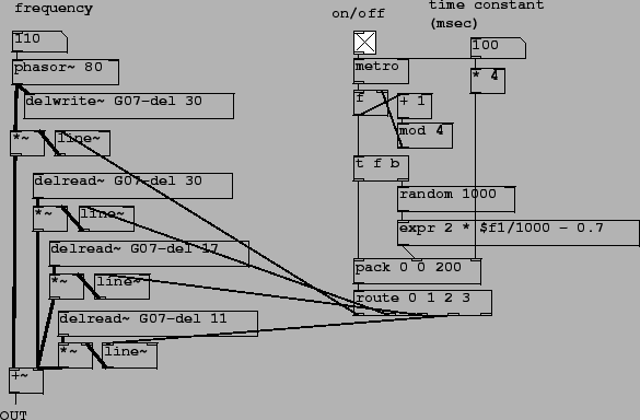
Patch G07.shaker.pd(Figure 7.30) shows a different way of extending the idea of a comb filter. Here we combine the input signal at four different time shifts (instead of two, as in the original non-recirculating comb filter), each at a different positive and/or negative gain. To do this, we insert the input signal into a delay line and tap it at three different points; the fourth ``tap" is the original, undelayed signal.
As a way of thinking about the frequency response of a four-tap comb filter, we consider first what happens when two of the four gains are close to zero. Then we end up with a simple non-recirculating comb filter, with the slight complication that the gains of the two delayed copies may be different. If they are both of the same sign, we get the same peaks and valleys as predicted in Section 7.3, only with the valleys between peaks possibly being more shallow. If they are opposite in sign, the valleys become peaks and the peaks become valleys.
Depending on which two taps we supposed were nonzero, the peaks and valleys are spaced by different amounts; the delay times are chosen so that 6 different delay times can arise in this way, ranging between 6 and 30 milliseconds. In the general case in which all the gains are non-zero, we can imagine the frequency response function varying continuously between these extremes, giving a succession of complicated patterns. This has the effect of raising and lowering the amplitudes of the partials of the incoming signal, all independently of the others, in a complicated pattern, to give a steadily time-varying timbre.
The right-hand side of the patch takes care of changing the gains of the input signal and its three time-shifted copies. Each time the metro object fires, a counter is incremented (the f, + 1, and mod 4 objects). This controls which of the amplitudes will be changed. The amplitude itself is computed by making a random number and normalizing it to lie between -0.7 and 1.3 in value. The random value and the index are packed (along with a third value, a time interval) and this triple goes to the route object. The first element of the triple (the counter) selects which output to send the other two values to; as a result, one of the four possible line~ objects gets a message to ramp to a new value.
If the time variation is done quickly enough, there is also a modulation effect on the original signal; in this situation the straight line segments used in this example should be replaced by modulating signals with more controllable frequency content; we will revisit this in the next chapter.