Generalizing the one-zero, one-pole filter above, supose we
place the zero at a point ![]() , a real number
close to, but less than, one. The pole, at the point
, a real number
close to, but less than, one. The pole, at the point ![]() , is similarly situated, and might be either greater than or
less than
, is similarly situated, and might be either greater than or
less than ![]() , i.e., to the right or left,
respectively, but with both
, i.e., to the right or left,
respectively, but with both ![]() and
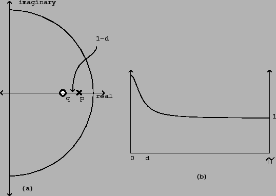
and ![]() within the unit circle. This situation is diagrammed in Figure
8.14.
within the unit circle. This situation is diagrammed in Figure
8.14.
At points of the circle far from ![]() and
and
![]() , the effects of the pole and the zero are
nearly inverse (the distances to themare nearly equal), so the
filter largely passes those frequencies unaltered. In the
neighborhood of
, the effects of the pole and the zero are
nearly inverse (the distances to themare nearly equal), so the
filter largely passes those frequencies unaltered. In the
neighborhood of ![]() and
and ![]() , on the other
hand, the filter will have a gain greater or less than one
depending on which of
, on the other
hand, the filter will have a gain greater or less than one
depending on which of ![]() or
or ![]() is
closer to the circle. This configuration therefore acts as a
low-frequency shelving filter. (To make a high-frequency shelving
filter we do the same thing, only placing
is
closer to the circle. This configuration therefore acts as a
low-frequency shelving filter. (To make a high-frequency shelving
filter we do the same thing, only placing ![]() and
and
![]() close to -1 instead of 1.)
close to -1 instead of 1.)
To find the parameters of a desired shelving filter, start with
a desired transition frequency ![]() (in angular
units) and a desired low-frequency gain
(in angular
units) and a desired low-frequency gain ![]() . First we
choose an average distance
. First we
choose an average distance ![]() , as pictured in the
figure, from the pole and the zero to theedge of the circle. For
small values of
, as pictured in the
figure, from the pole and the zero to theedge of the circle. For
small values of ![]() , the region of influence (the
crossover frequency) is about
, the region of influence (the
crossover frequency) is about ![]() radians.
radians.
Then put the pole at
![]() and the zero at
and the zero at
![]() . The gain at zero
frequency is then
. The gain at zero
frequency is then