Sometimes an audio signal carries an unwanted constant offset, or in other words, a zero-frequency component. For example, the waveshaping spectra of Section 5.3 almost always contain a constant component. This is inaudible, but, since it specifes electrical power that is converted to heat in your speakers, its presence reduces the level of loudness you can reach without distortion. Another name for a constant signal component is ``DC", meaning ``direct current".
An easy and practical way to remove the zero-frequency component
from an audio signal is to use a one-pole lowpass filter to extract
it, and then subtract the result from the signal. The resulting
transfer function is one minus the transfer function of the
lowpass, giving:
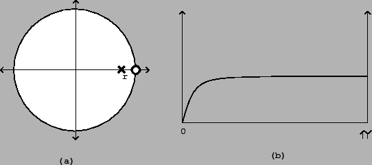
By examining the right-hand side of the equation (comparing it
to the general formula for compound filters), we see that there is
still a pole at the real number ![]() , and there is now
also a zero at the point
, and there is now
also a zero at the point ![]() . The pole-zero plot is as
shown in Figure 8.13 part (a), and the
frequency response in part (b). (From here on, we will only plot
frequency responses to the Nyquist frequency
. The pole-zero plot is as
shown in Figure 8.13 part (a), and the
frequency response in part (b). (From here on, we will only plot
frequency responses to the Nyquist frequency ![]() ; in the previous example we plotted it all the way up to
the sample rate,
; in the previous example we plotted it all the way up to
the sample rate, ![]() .)
.)
 |