Sometimes a filter is applied to get a desired phase change,
rather than to alter the amplitudes of the frequency components of
a sound. In this situation we would need a way to design a filter
with a constant, unit frequency response but which changes the
phase of an incoming sinusoid in a way that depends on its
frequency. We have already seen in Chapter 7 that a delay of length
![]() introduces a phase change of
introduces a phase change of ![]() , at the angular frequency
, at the angular frequency ![]() .
Another class of filters, called all-pass filters, can make phase changes which
are more widely variable functions of
.
Another class of filters, called all-pass filters, can make phase changes which
are more widely variable functions of ![]() .
.
To design an all-pass filter, we start with two facts: first, an elementary recirculating filter and an elementary non-recirculating one cancel each other out perfectly if they have the same gain coefficient. In other words, if a signal has been put through a one-zero filter, either real or complex, the effect can be reversed by sequentially applying a one-pole filter, and vice versa.
The second fact is that the elementary non-recirculating filter of the second form has the same frequency response as that of the first form; they differ only in phase response. So if we combine an elementary recirculating filter with an elementary non-recirculating one of the second form, the frequency responses cancel out (to a flat gain independent of frequency) but the phase response is not constant.
To find the transfer function, we choose the same complex number
![]() as coefficient for both elementary
filters and multiply their transfer functions:
as coefficient for both elementary
filters and multiply their transfer functions:
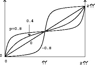 |
Complex coefficients give similar phase response curves, but the
frequencies at which they cross the diagonal line in the figure are
shifted according to the argument of the coefficient ![]() .
.