


Next: Non-recirculating filter, second form Up:
Designing filters Previous: Designing
filters Contents Index
Elementary non-recirculating filter
We generalize the non-recirculating comb filter to the design
shown in figure 8.7, called the non-recirculating elementary filter, of the first
form.
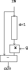
Figure 8.7: A delay
network with a single-sample delay and a complex gain  . This is the non-recirculating elementary filter, first
form. Compare the simpler non-recirculating comb filter shown in
Figure 7.3, which corresponds
to choosing
. This is the non-recirculating elementary filter, first
form. Compare the simpler non-recirculating comb filter shown in
Figure 7.3, which corresponds
to choosing  here.
here.
 |
To find the frequency response, as in Chapter 7 we feed the
delay network a complex sinusoid
 whose frequency is
 , so that as before,
 . The
. The  th sample
of the input is
th sample
of the input is  and that of the output is
so the transfer function is
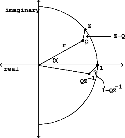
This can be represented graphically as shown in Figure 8.8. Suppose we write the coefficient in polar form:
Then the gain of the filter is the distance from the point
to the point  in the complex
plane. Analytically we can see this because
in the complex
plane. Analytically we can see this because
Graphically, the number  is just the number
rotated backwards (clockwise) by the angular
frequency
is just the number
rotated backwards (clockwise) by the angular
frequency  of the incoming sinusoid. The
value
of the incoming sinusoid. The
value
 is the distance from
to
is the distance from
to  in the
complex plane, which is equal to the distance from to
.
in the
complex plane, which is equal to the distance from to
.
Figure 8.8: Diagram for
calculating the frequency response of the non-recirculating
elementary filter (Figure 8.7). The
frequency response is given by the length of the segment connecting
to  in the complex
plane.
in the complex
plane.
 |
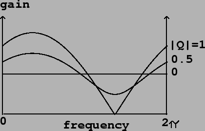
As the frequency of the input sweeps from 0 to  , the point travels couterclockwise
around the unit circle. At the point where
, the point travels couterclockwise
around the unit circle. At the point where
 , the distance is at a
minimum, equal to
, the distance is at a
minimum, equal to  . The maximum occurs which
is at the opposite point of the circle.
Figure 8.9 shows the transfer function for
three different values of
. The maximum occurs which
is at the opposite point of the circle.
Figure 8.9 shows the transfer function for
three different values of  .
.
Figure 8.9: Frequency
response of the elementary non-recirculating filter Figure 8.7. Three values of are used, all
with the same argument (-2 radians), but with varying absolute
value.
 |
Next: Non-recirculating filter, second form Up:
Designing filters Previous: Designing
filters Contents Index
Miller Puckette 2006-03-03