Patches H01.low-pass.pd, H02.high-pass.pd, and H03.band-pass.pd (Figure 8.28) show Pd's built-in filters, which implement filter designs described in sections 8.3.1, 8.3.2 and 8.1.2. Two of the patches also use a noise generator we have not introduced before; so we now introduce four new Pd objects:
![]() : One-pole low-pass filter. The left inlet takes a signal
to be filtered, and the right inlet takes control messages to set
the cutoff frequency of the filter. The filter is normalized so
that the gain is one at frequency 0.
: One-pole low-pass filter. The left inlet takes a signal
to be filtered, and the right inlet takes control messages to set
the cutoff frequency of the filter. The filter is normalized so
that the gain is one at frequency 0.
![]() : One-pole, one-zero high-pass filter, with the same
inputs and outputs as lop~, normalized to have a gain of
one at the Nyquist frequency.
: One-pole, one-zero high-pass filter, with the same
inputs and outputs as lop~, normalized to have a gain of
one at the Nyquist frequency.
![]() : Resonant filter. The middle inlet takes control
messages to set the center qrequency, and the right inlet to set
``q".
: Resonant filter. The middle inlet takes control
messages to set the center qrequency, and the right inlet to set
``q".
![]() : Outputs white noise. Each sample is an independent
pseudo-random number, uniformly distributed from -1 to 1.
: Outputs white noise. Each sample is an independent
pseudo-random number, uniformly distributed from -1 to 1.
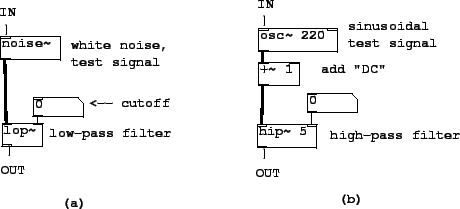 |
As shown in Figure 8.28, the first three example patches demonstrate these three filters. The lop~ and bp~ objects are demonstrated with noise as input; hip~ as shown is used to remove the DC (zero frequency) component of a signal.