No finite set of prefabricated filters could fill every possible need, and so Pd provides the elementary filters of sections 8.2.1-8.2.3 in raw form, so that the user supplies the filter coefficients explicitly. In this section we will describe patches that realize the shelving and peaking filters of sections 8.3.3 and 8.3.5 directly from elementary filters. First we introduce the six Pd objects that realize elementary filters:
![]() ,
,
![]() ,
,
![]() : elementary filters with real-valued coefficients
operating on real-valued signals. The three implement
non-recirculating filters of the first and secton types, and the
recirculating filter. They all have one inlet, at right, to supply
the coefficient. For rzero~ and rpole~ this
coefficent gives the location of the zero or pole. The inlet for
the coefficient (as well as the left inlet for the signal to
filter) take audio signals. No stability check is performed.
: elementary filters with real-valued coefficients
operating on real-valued signals. The three implement
non-recirculating filters of the first and secton types, and the
recirculating filter. They all have one inlet, at right, to supply
the coefficient. For rzero~ and rpole~ this
coefficent gives the location of the zero or pole. The inlet for
the coefficient (as well as the left inlet for the signal to
filter) take audio signals. No stability check is performed.
![]() ,
,
![]() ,
,
![]() : elementary filters with complex-valued coefficients,
operating on complex-valued signals, corresponding to the
real-valued ones above. Instead of two inlets and one outlet, each
of these filters has four inlets (real and imaginary part of the
signal to filter, and real and imaginary part of the coefficient)
and two outlets for the complex-valued output of the filter.
: elementary filters with complex-valued coefficients,
operating on complex-valued signals, corresponding to the
real-valued ones above. Instead of two inlets and one outlet, each
of these filters has four inlets (real and imaginary part of the
signal to filter, and real and imaginary part of the coefficient)
and two outlets for the complex-valued output of the filter.
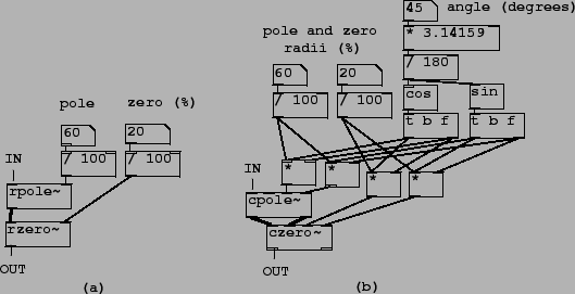
The example patches use a pair of abstractions to graph the frequency and phase responses of filters as explained in Patch H10.measurement.pd. Patch H11.shelving.pd (Figure 8.32, part (a)) shows how to make a shelving filter. One elementary non-recirculating filter (rzero~) and one elementary recirculating one (rpole~) are put in series. As Section 8.3.9 suggests, the rzero~ object is placed first.
Patch H12.peaking.pd shows the peaking filter (part (b) of the
figure). Here the pole and the zero are rotated by an angle
![]() to control the center frequency of the
filter. The bandwidth and center frequency gain are equal to the
shelf frequency and the DC gain of the corresponding shelving
filter.
to control the center frequency of the
filter. The bandwidth and center frequency gain are equal to the
shelf frequency and the DC gain of the corresponding shelving
filter.
Patch H13.butterworth.pd demonstrates a three-pole, three-zero
Butterwirth shelving filter. The filter itself is an abstraction,
butterworth3~, for easy re-use.