In the previous chapter we saw that a delay network can have a non-uniform frequency response, in other words, a gain that varies as a function of frequency. Delay networks also typically affect the phase of incoming signals in ways that depend on frequency. If the delay times used are short, the frequency-dependent gain and phase change become the best way of describing the effect of the delay network on its input. Delay networks which are designed specifically to effect particular amplitude or phase changes on their inputs are called filters.
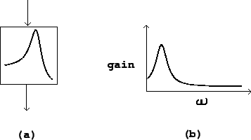 |
In block diagrams, filters are shown as in figure 8.1, part (a). The curve shown within the block gives a qualitative representation of the filter's frequency response (as defined in section 7.3). This frequency response may vary with time, and depending on the design of the filter, one of more controls (or additional audio inputs) might be used to change it.
Suppose, still following the procedure of section 7.3, we put a unit-amplitude,
complex-valued sinusoid with angular frequency ![]() into a filter. We expect to get out a sinusoid of the
same frequency and some amplitude, which depends on
into a filter. We expect to get out a sinusoid of the
same frequency and some amplitude, which depends on ![]() . This gives us a complex-valued function
. This gives us a complex-valued function ![]() , which is called the transfer function of the filter.
, which is called the transfer function of the filter.
The frequency response is the gain as a function of the
frequency ![]() . It is is equal to the absolute
value of the transfer function. A filter's frequency response is
customarily graphed as in Figure 8.1, part
(b). An incoming unit-amplitude sinusoid of frequency
. It is is equal to the absolute
value of the transfer function. A filter's frequency response is
customarily graphed as in Figure 8.1, part
(b). An incoming unit-amplitude sinusoid of frequency ![]() comes out of the filter with amplitude
comes out of the filter with amplitude ![]() .
.
It is sometimes also useful to know the phase response of the
filter, equal to
![]() . For a fixed frequency
. For a fixed frequency
![]() , the filter's output phase will be
, the filter's output phase will be
![]() radians ahead of its input
phase.
radians ahead of its input
phase.
The design and use of filters is a huge subject, because the wide range of uses a filter might be put to encourages a wide variety of filter design processes. In some uses a filter must exactly follow a prescribed frequency response, in others it is important to minimize computation time, in others the phase response is important, and in still others the filter must behave well when its parameters change quickly with time.